Display apparatus and drive method therefor

Active Publication Date: 2006-09-28
SOLAS OLED LTD
View PDF33 Cites 44 Cited by
  • Summary
  • Abstract
  • Description
  • Claims
  • Application Information

AI Technical Summary

Benefits of technology

[0013] One advantage of the invention lies in that the display can emit light on a current with the adequate current value and the ratio of the luminous area to the non-luminous area is high, and another advantage lies in that the display has a structure which is easy to manufacture.
[0014] To overcome the aforementioned problems, a display apparatus according to one aspect of the invention comprises:
[0015] a plurality of pixels respectively laid out at intersections of plural scan lines and plural signal lines in a display area and each having an optical element which performs an optical operation based on a current value of a drive current flowing therethrough and a pixel circuit which supplies the drive current to the optical element; and
[0016] a current control driver which is arranged in an other area than the display area, is connected to each of the signal lines and reduces a current

Problems solved by technology

There had occurred an additional problem such that the probability of occurrence of an in-plane variation in the current characteristics of the transistors 705 and 706 which serve as a current mirro

Method used


Image

  • Display apparatus and drive method therefor
  • Display apparatus and drive method therefor
  • Display apparatus and drive method therefor

Examples


first embodiment

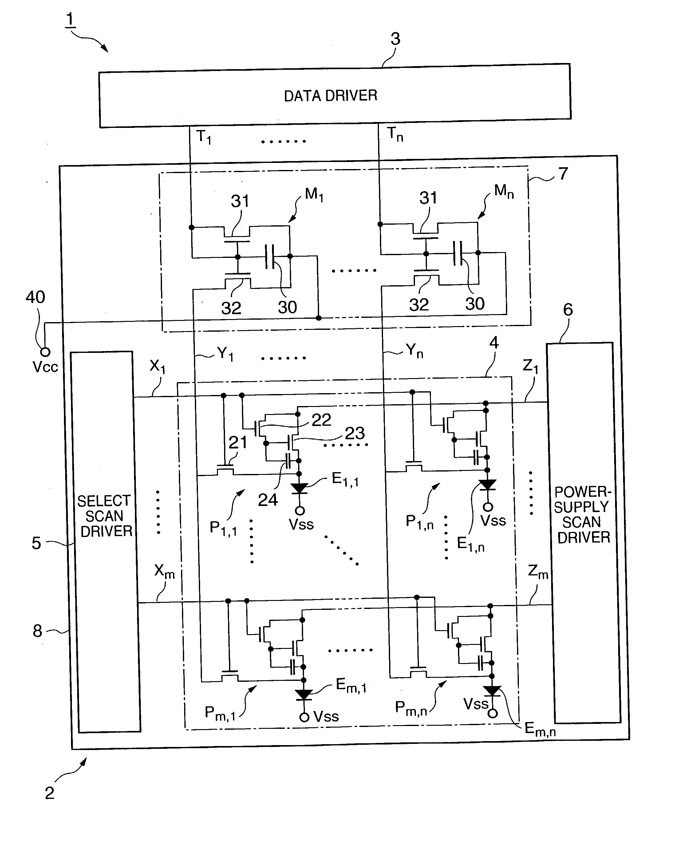
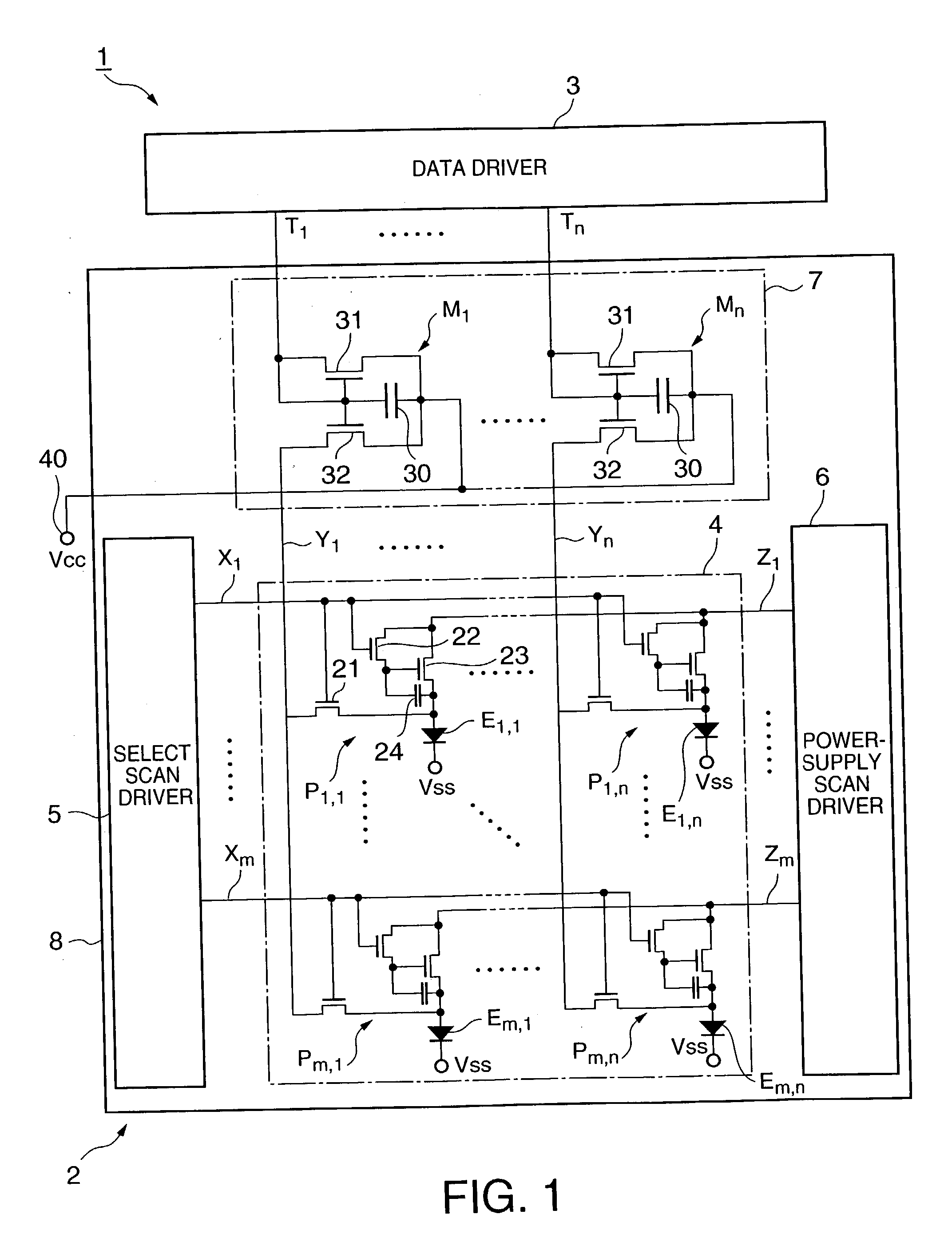
[0054]FIG. 1 is a circuit diagram illustrating a display apparatus to which the invention is adapted. As shown in FIG. 1, the basic structure of the display apparatus 1 has an organic EL display panel 2 which provides color display by an active matrix driving system, and a data driver (gradation signal output means) 3 which outputs gradation signals, represented by current values corresponding to the gradations of image data, to the organic EL display panel 2 in parallel.

[0055] The organic EL display panel 2 has a basic structure that includes a transparent substrate 8, a display section 4 or the display area on which an image is substantially displayed, a select scan driver 5 provided around the display section 4 or in the non-display area, a power-supply scan driver 6 and a current conversion section 7. Those circuits 4 to 7 are formed on the transparent substrate 8. A current control driver has the current conversion section 7 and the data driver 3.

[0056] In the display section...

second embodiment

[0120]FIG. 9 is a block diagram illustrating a display apparatus 101 of a different mode from the display apparatus 1 according to the first embodiment. As shown in FIG. 9, the display apparatus 101 has an organic EL display panel 102 which provides color display by the active matrix driving system and a shift register 103.

[0121] The organic EL display panel 102 has a basic structure that includes a transparent substrate 8, a display section 4 or the display area on which an image is substantially displayed, a select scan driver 5 provided around the display section 4 or in the non-display area, a power-supply scan driver 6 and a current conversion section 107. Those circuits 4 to 6 and 107 are formed on the transparent substrate 8. The display section 4, the select scan driver 5, the power-supply scan driver 6 and the transparent substrate 8 are the same as those of the display apparatus 1 of the first embodiment. In case of the P+ substrate 101 of the second embodiment, therefore...


PUM


Abstract

Disclosed is a high-definition display apparatus which allows a write current having an adequate value to flow. The display apparatus comprises a plurality of signal lines, a plurality of optical elements which presents display as a drive current equal in value to a write current flowing in the signal lines flows, and a current control driver which is connected to one ends of the signal lines, reduces the current value of a gradation signal by a current reduction ratio and lets the write current flow in the signal lines.

Description

BACKGROUND OF THE INVENTION [0001] 1. Field of the Invention [0002] The present invention relates to a display apparatus equipped with optical elements, pixel by pixel, which perform an optical operation according to a current value, particularly, optical elements which emit light with a brightness according to the current value, and a drive method for the display apparatus. [0003] 2. Description of the Related Art [0004] In general, there are two types of display apparatuses: a passive driving type and an active matrix driving type which has switching transistors provided pixel by pixel. In a liquid crystal display of the active matrix driving type, as shown in FIG. 11, a liquid crystal element 501 having a liquid crystal which also serves as a capacitor, and a transistor 502 which serves as a switching element are provided for each pixel. In the active matrix driving type, when a data driver applies a voltage for controlling the transmittivity of the liquid crystal to a signal lin...

Claims


Application Information

Patent Timeline
IPC IPC(8): G09G3/30G09G3/20G09G3/32H01L51/50H05B33/14
CPCG09G3/325G09G3/3275G09G2300/0408G09G2300/0417G09G2300/0809H01L27/3297G09G2300/0866G09G2320/0295G09G2320/043H01L27/3244G09G2300/0842H10K59/12H10K59/131
Inventor MORISHIGE, MORIOSHIRASAKI, TOMOYUKIYAMADA, HIROYASU
Owner SOLAS OLED LTD
Why Eureka
Try Eureka