Fuel cell

a fuel cell and fuel gas technology, applied in the field of fuel cells, can solve the problems of affecting the performance of power generation, affecting the efficiency of power generation, and affecting the electrode catalysts of the electrolyte electrode assembly, and achieve the effect of simple structure, smooth and reliable discharge of retained water

Active Publication Date: 2006-09-28
HONDA MOTOR CO LTD
View PDF11 Cites 28 Cited by
  • Summary
  • Abstract
  • Description
  • Claims
  • Application Information

AI Technical Summary

Benefits of technology

[0011] A main object of the present invention is to provide a fuel cell having simple structure which makes it possible to smoothly and reliably discharge the retained water from electrode catalyst layers of an electrolyte electrode assembly and achieve the desired power generation performance.

Problems solved by technology

Thus, the oxygen-containing gas passages or the fuel gas passages may be narrowed or clogged due to the retained water.
Under the circumstances, the flows of the oxygen-containing gas and the fuel gas tend to be disturbed undesirably, and the power generation performance is degraded.
As a result, in particular, when the temperature is low, the retained water may be frozen, damaging the electrode catalysts of the electrolyte electrode assembly.

Method used


Image

  • Fuel cell
  • Fuel cell
  • Fuel cell

Examples


first embodiment

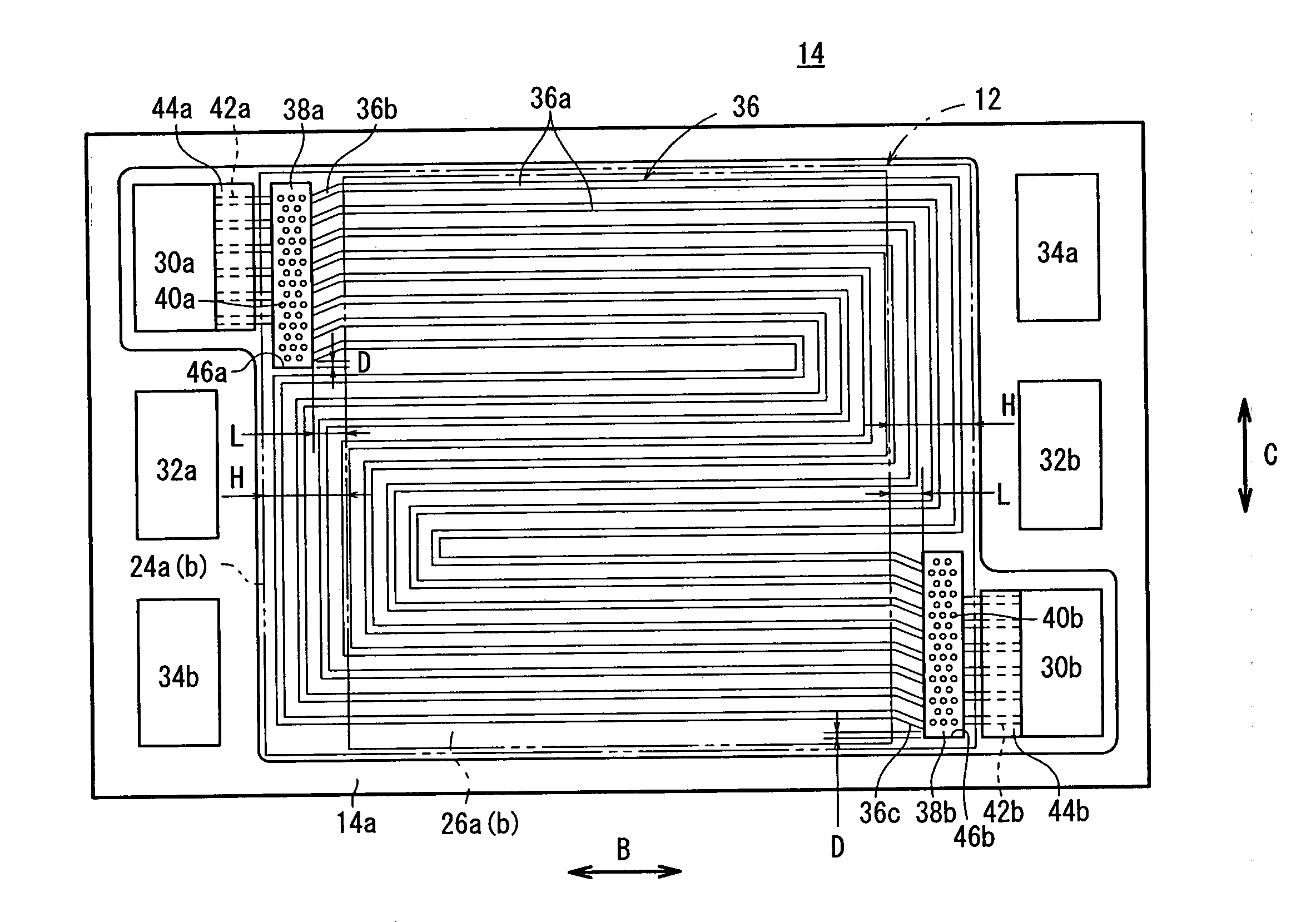
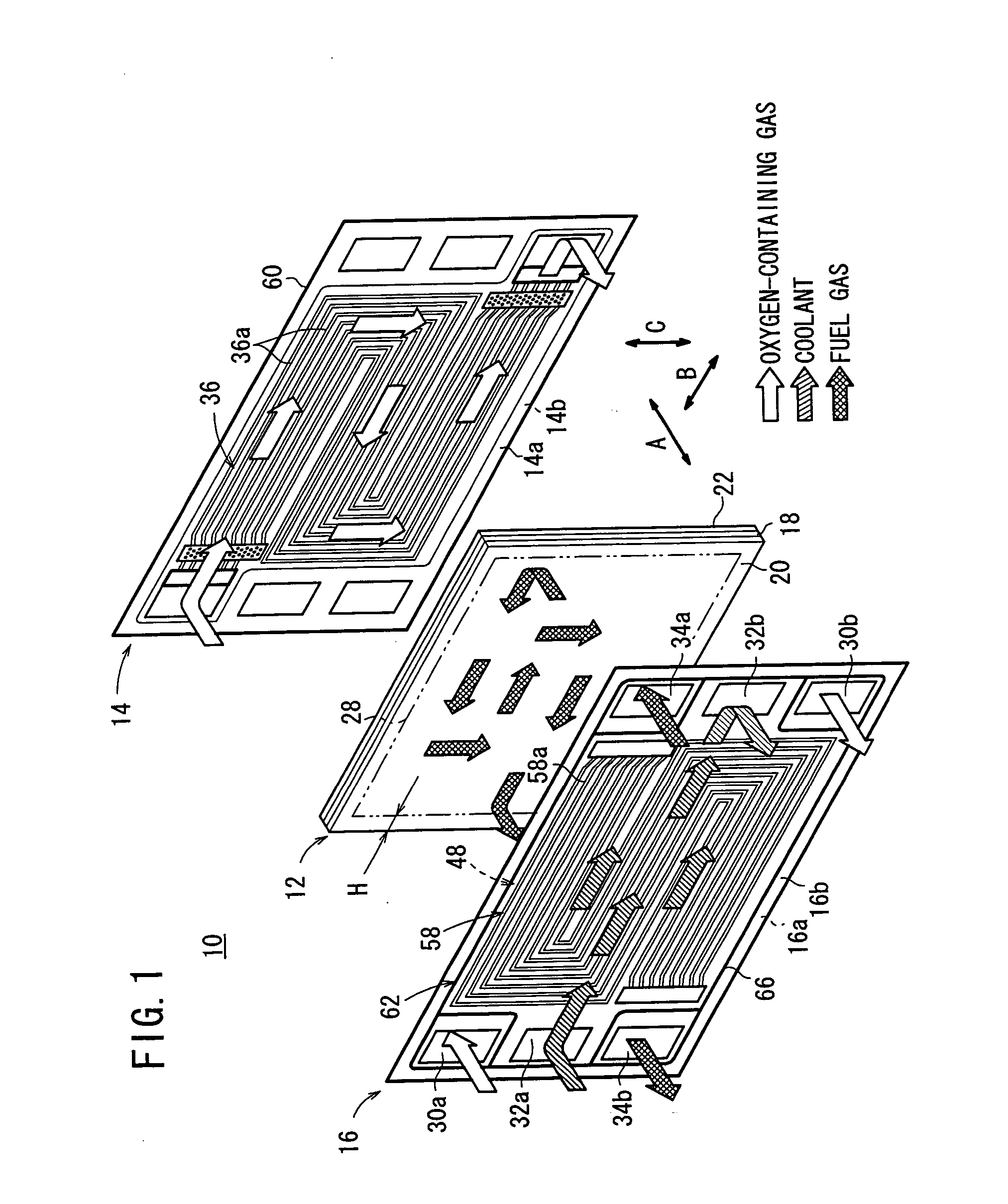
[0045]FIG. 1 is an exploded perspective view showing main components of a fuel cell 10 according to the present invention. A membrane electrode assembly (electrolyte electrode assembly) 12 and first and second metal separators 14, 16 are stacked together in a horizontal direction indicated by an arrow A. In general, a plurality of fuel cells 10 are stacked together to form a fuel cell stack.

[0046] The membrane electrode assembly 12 includes an anode 20, a cathode 22, and a solid polymer electrolyte membrane 18 interposed between the anode 20 and the cathode 22. The solid polymer electrolyte membrane 18 is formed by impregnating a thin membrane of perfluorosulfonic acid with water, for example.

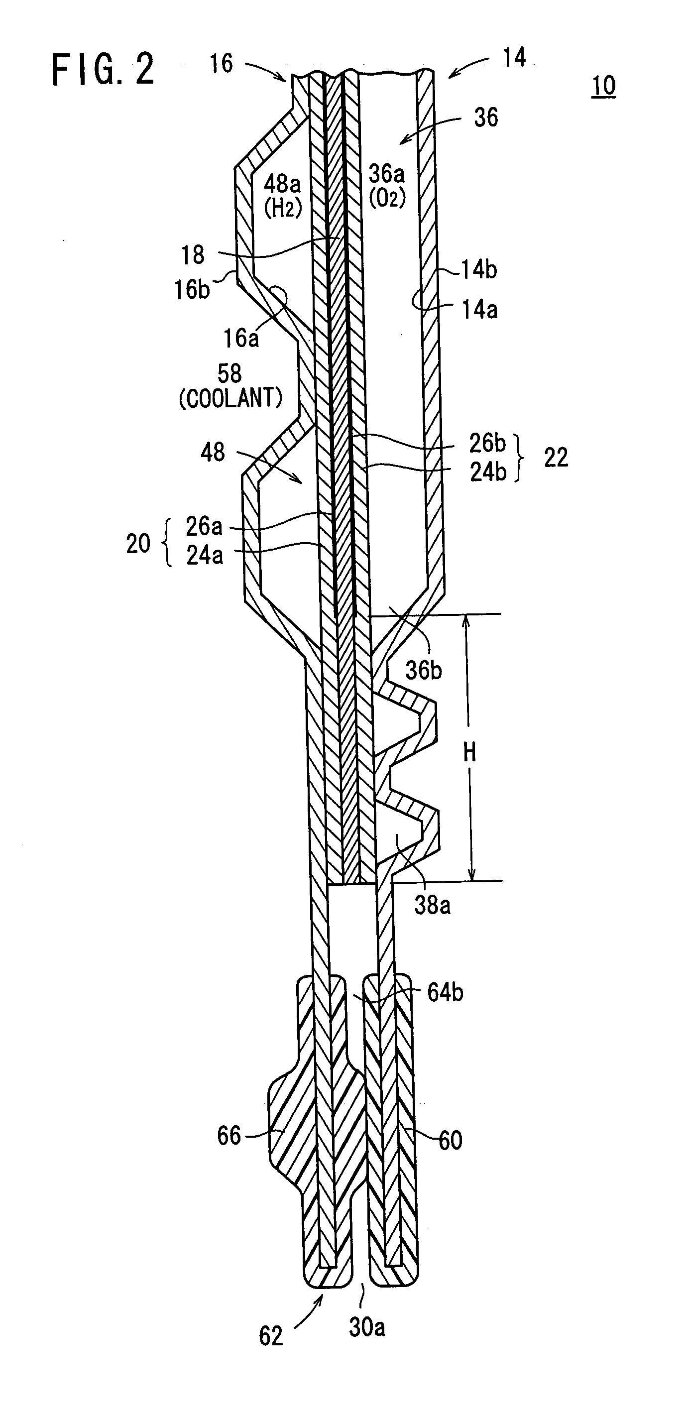
[0047] As shown in FIG. 2, each of the anode 20 and the cathode 22 has a gas diffusion layer 24a, 24b such as a carbon paper, and an electrode catalyst layer 26a, 26b of platinum alloy supported on porous carbon particles. The carbon particles are deposited uniformly on the surface of the gas ...

third embodiment

[0076]FIG. 6 is a front view showing a first metal separator 90 of a fuel cell according to the present invention.

[0077] The first metal separator 90 has an oxygen-containing gas flow field (reactant gas flow field) 92 comprising a plurality of oxygen-containing gas flow grooves 92a in a serpentine pattern. At ends 92b, 92c of the oxygen-containing gas flow grooves 92a, every two grooves are merged such that one of the two grooves is curved, and the merged grooves are connected to the inlet buffer 50a and the outlet buffer 50b. Because the ends 92b, 92c are extended outwardly from the electrode catalyst layers 26a, 26b by the distance L, the flow rate of the purging air is not decreased. In the structure, the same advantages as in the case of the first and second embodiments can be obtained. For example, the retained water can be discharged from the electrode catalyst layers 26a, 26b smoothly and reliably.

fourth embodiment

[0078]FIG. 7 is a front view showing a first metal separator 100 according to the present invention. The first metal separator 100 has an oxygen-containing gas flow field (reactant gas flow field) 102 comprising a plurality of oxygen-containing gas flow grooves 102a in a serpentine pattern. Ends 102b, 102c of the oxygen-containing gas flow grooves 102a are extended outwardly from the electrode catalyst layers 26a, 26b by the distance L toward an inlet buffer 104a and an outlet buffer 104b.

[0079] A plurality of bosses 106a, 106b are formed in the inlet buffer 104a and the outlet buffer 104b. The distance S1 between the ends 102b, 102c of the oxygen-containing gas flow grooves 102a and the nearest bosses 106a, 106c is substantially the same as the distance S2 of the groove width of the oxygen-containing gas flow grooves 102a.

[0080] In the fourth embodiment, when the purging air is supplied to the oxygen-containing gas flow grooves 102a of the oxygen-containing gas flow field 102 at ...


PUM

PropertyMeasurementUnit
distanceaaaaaaaaaa
distanceaaaaaaaaaa
distanceaaaaaaaaaa

Abstract

An oxygen-containing gas flow field is formed on a surface of a first metal separator. The oxygen-containing gas flow field is connected between an oxygen-containing gas supply passage and an oxygen-containing gas discharge passage. The oxygen-containing gas flow field comprises oxygen-containing gas flow grooves, and ends of the oxygen-containing gas flow grooves are extended outwardly beyond ends of electrode catalyst layer of a membrane electrode assembly, and connected to an inlet buffer and an outlet buffer. When the purging process is performed at the time of stopping operation of the fuel cell, the purging air supplied to the oxygen-containing gas flow field discharges water retained in the electrode catalyst layers from the ends to the outlet buffer.

Description

BACKGROUND OF THE INVENTION [0001] 1. Field of the Invention [0002] The present invention relates to a fuel cell formed by stacking an electrolyte electrode assembly and separators horizontally. The electrolyte electrode assembly includes a pair of electrodes and an electrolyte interposed between the electrodes. A reactant gas flow field is formed between the electrolyte electrode assembly and one of separators sandwiching the electrolyte electrode assembly for supplying a reactant gas along a surface of the electrode, and a reactant gas passage connected to an inlet or an outlet of the reactant gas flow field extends through the fuel cell. [0003] 2. Description of the Related Art [0004] For example, a solid polymer electrolyte fuel cell employs a solid polymer electrolyte membrane. The solid polymer electrolyte membrane is an ion exchange membrane. In the fuel cell, an anode and a cathode each including an electrode catalyst (electrode catalyst layer) and a porous carbon (gas diffu...

Claims


Application Information

Patent Timeline
Patent Type & Authority Applications(United States)
IPC IPC(8): H01M8/02H01M4/94H01M50/77
CPCH01M8/0258H01M8/0263H01M8/0286Y02E60/50H01M8/0265H01M8/241H01M8/2483H01M8/04228H01M8/2457
Inventor YOSHIDA, HIROMICHIINAI, SHIGERUKOSHINUMA, MINORUJINBA, RYOSUGIURA, SEIJIMITSUTA, NAOKIHAYASHI, KATSUMI
Owner HONDA MOTOR CO LTD
Why Eureka
Try Eureka