Electric air pump apparatus and evaporation fuel treatment system
a technology of evaporation fuel treatment and air pump, which is applied in the direction of combustion air/fuel air treatment, process and machine control, instruments, etc., can solve the problems of deteriorating mount-properties of the engine room of the vehicle, secondary air supply system, and insufficient negative pressure, so as to improve the control responsiveness of the flow opening valve and reduce the size of the valve drive parts
- Summary
- Abstract
- Description
- Claims
- Application Information
AI Technical Summary
Benefits of technology
Problems solved by technology
Method used
Image
Examples
first embodiment
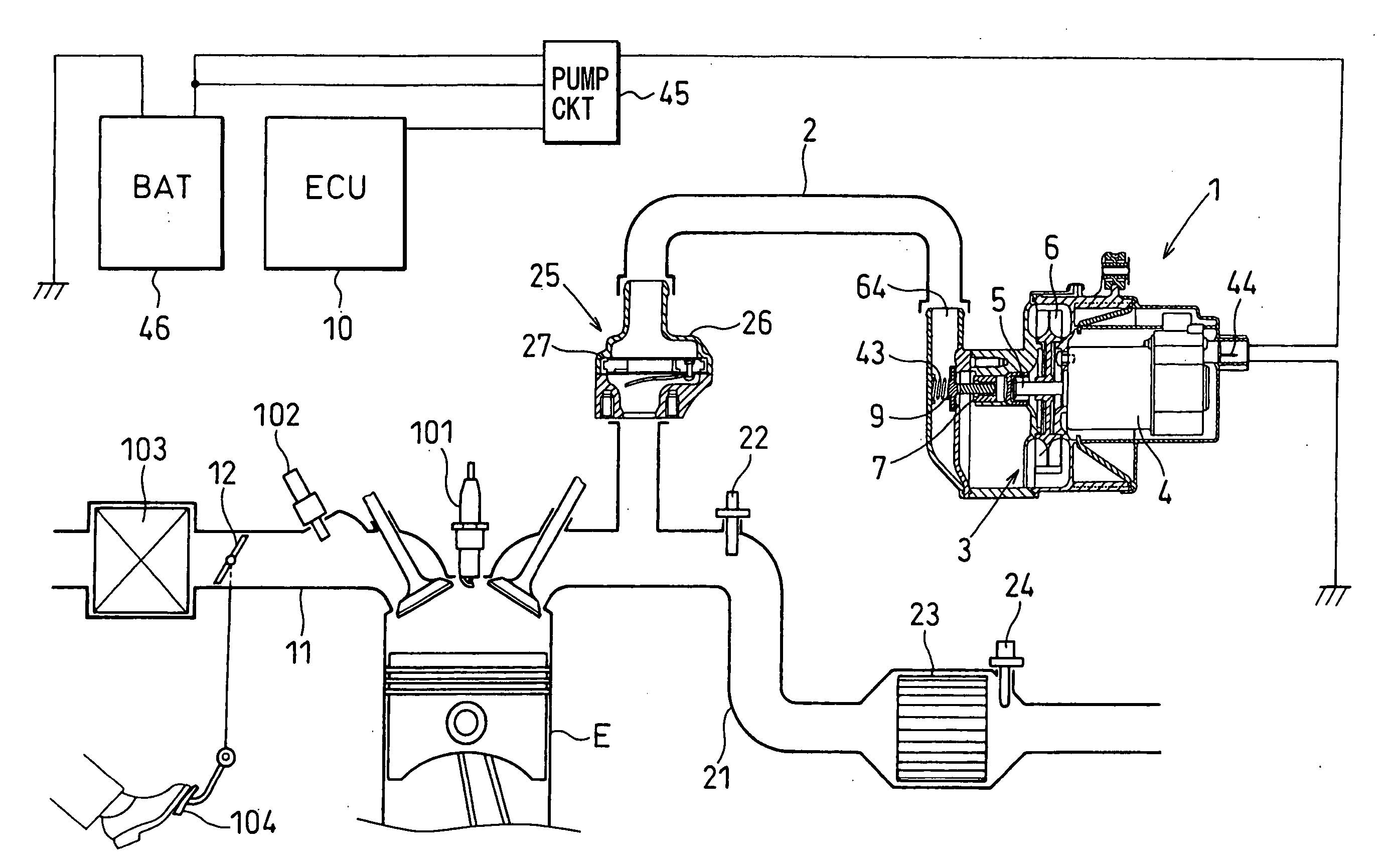
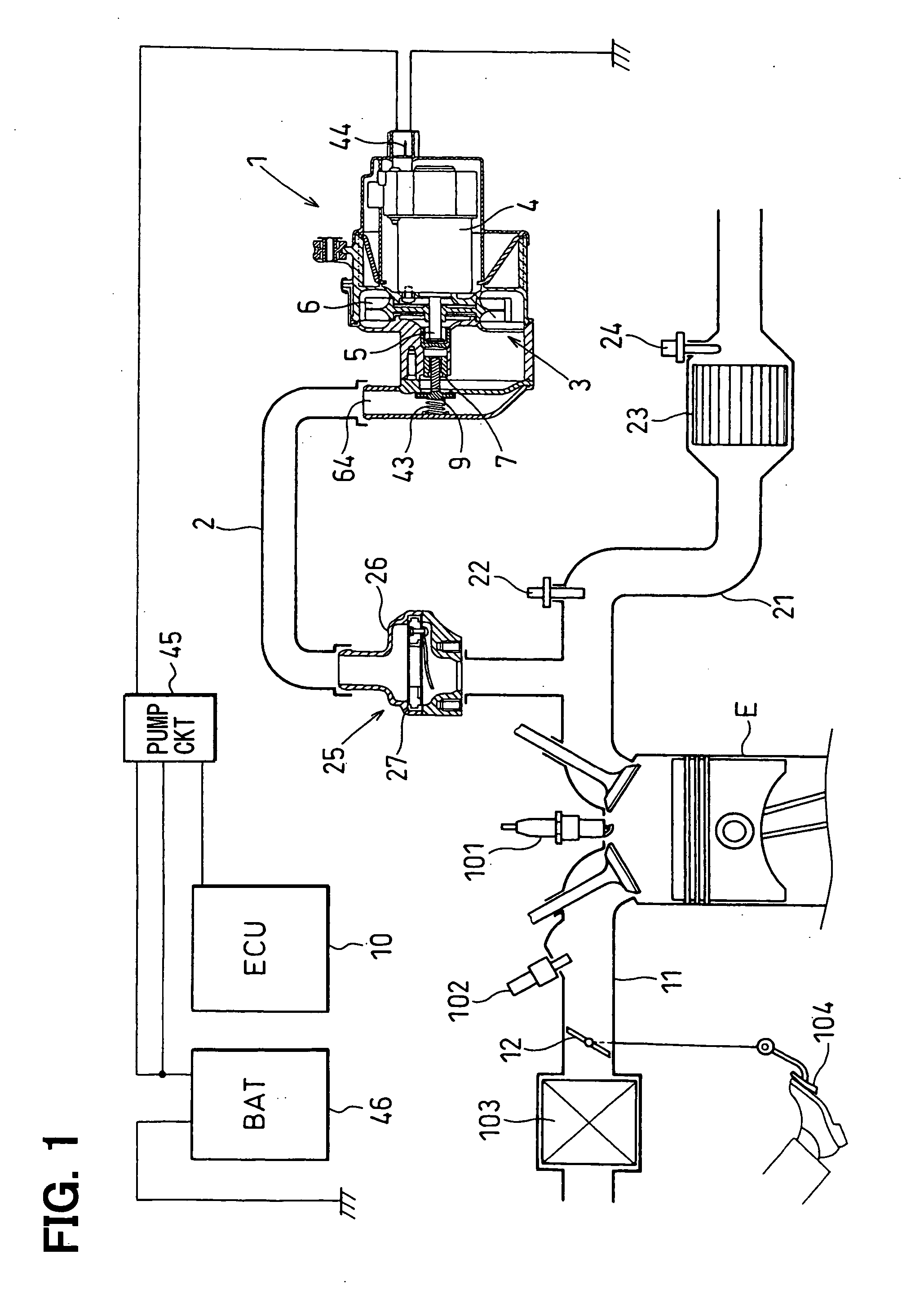
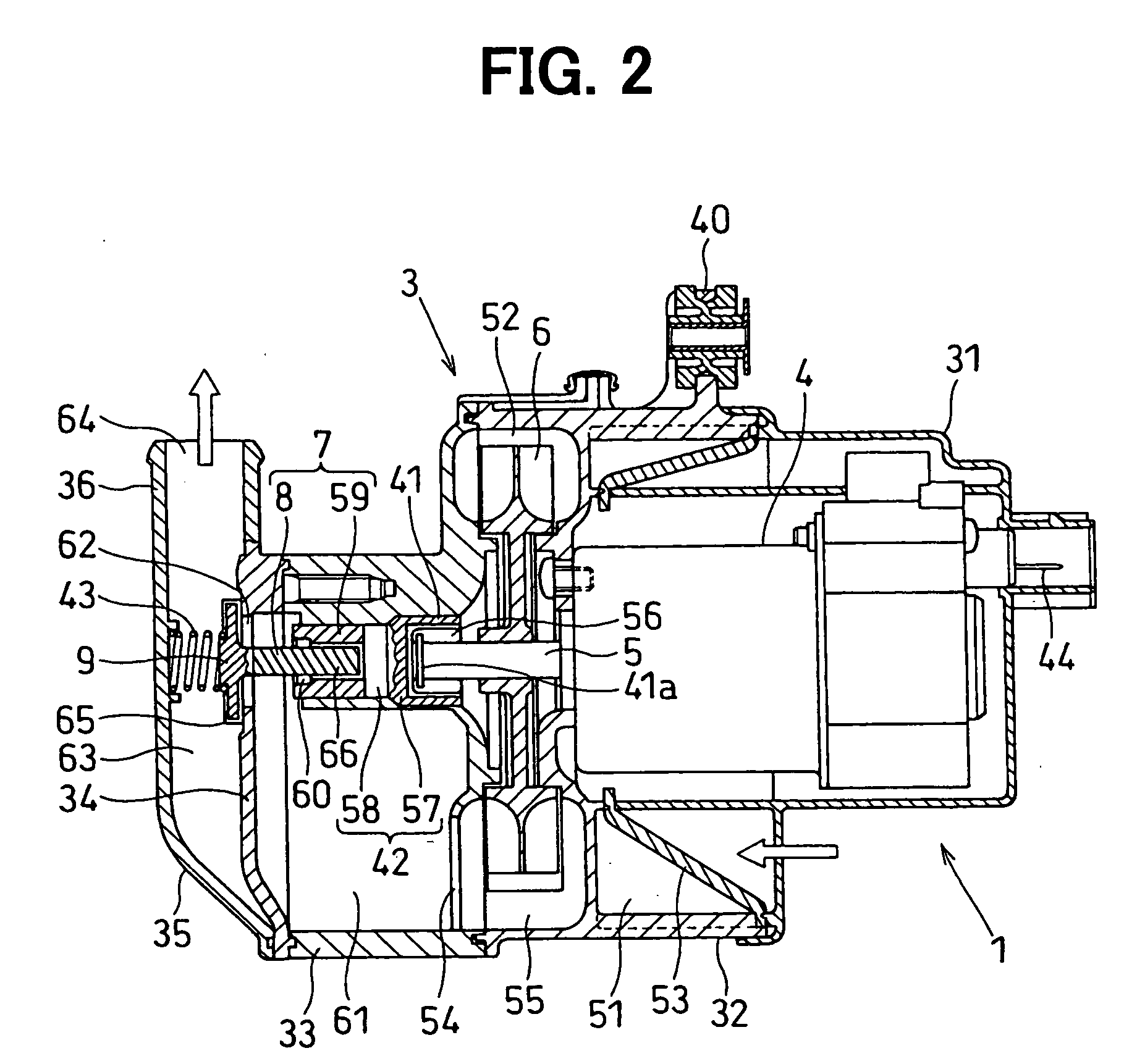
[0041] Referring to FIGS. 1 and 2, a secondary air supply system is mounted in an engine room for a vehicle such as an automobile and is provided with an electric air pump unit 1. The secondary air supply system introduces secondary air generated in a secondary airflow pipe (airflow pipe) 2 at the time of starting an internal combustion engine (engine) E such as a gasoline engine into a three-way catalyst converter 23 to promote warming-up of the three-way catalyst.
[0042] The engine E produces a power output by heat energy obtained by burning a mixture of intake air and fuel in a combustion chamber. The engine E is provided with a cylinder block slidably supporting a piston and a cylinder head including an intake port connected to a downstream end of an engine intake pipe 11 including an intake manifold and an exhaust port connected to an upstream end of an engine exhaust pipe 21 including an exhaust manifold. The intake port and the exhaust port each are opened / closed by an intake...
second embodiment
[0075]FIGS. 3 and 4 show a second embodiment of the present invention. FIG. 3 is a block diagram showing an entire arrangement of a secondary air supply system. FIG. 4 is a cross section showing an electric air pump unit.
[0076] In the second embodiment, the friction plate 57 of the torque limiter 42 instead of the clutch inner of the centrifugal clutch 41 is mounted integrally with the front end of the motor shaft 5 in the axial direction by joint means such as welding. This causes elimination of the plurality of the clutch weights 56, the clutch inner, the clutch outer and the like, leading to further reduction in the number of components and in assembly labors as compared to the first embodiment. The centrifugal clutch 41 may be provided between the motor shaft 5 and the torque limiter 42. The coil spring 43 may be provided or not provided. In the electric motor 4 of the second embodiment, flow directions of a pump drive current supplied to the armature winding are set as two dir...
third embodiment
[0080]FIGS. 5 and 6 show a third embodiment of the present invention. FIG. 5 is a cross section showing an electric air pump unit.
[0081] In the third embodiment, a stopper 67 is provided in the second valve seat of the fifth case 35. The valve 9 gets in contact with the stopper 67 when the valve 9 opens. In the electric motor 4 in the third embodiment, the rotational directions of the motor shaft 5 are set as two directions which are forward and reverse directions in the same way as in the second embodiment. As a result, the valve 9 can be driven and closed without provision of the coil spring 43, thereby further reduction in the number of components and in assembly labors as compared to the first embodiment. The ECU 10 in the third embodiment includes a known microcomputer therein in the same as in the first embodiment. When the ignition switch is ON and the engine E starts to operate, the ECU 10 adjusts electric power supplied to the electric motor 4 based upon control programs s...
PUM
 Abstract
Description
Claims
Application Information
 - R&D
- Intellectual Property
- Life Sciences
- Materials
- Tech Scout
- Unparalleled Data Quality
- Higher Quality Content
- 60% Fewer Hallucinations
Browse by: Latest US Patents, China's latest patents, Technical Efficacy Thesaurus, Application Domain, Technology Topic, Popular Technical Reports.
© 2025 PatSnap. All rights reserved.Legal|Privacy policy|Modern Slavery Act Transparency Statement|Sitemap|About US| Contact US: help@patsnap.com


