Self-cleaning strainer

US20060219645A1Inactive Publication Date: 2006-10-05CONTINUUM DYNAMICS

Image

  • Self-cleaning strainer
  • Self-cleaning strainer
  • Self-cleaning strainer

Examples


Embodiment Construction

[0033] The present invention relates to externally powered, self-cleaning strainers having a missile shield and a low pressure drop across the strainer.

[0034] To understand the inventive concepts of the present invention it is useful to refer to the attached drawings in which like numbers refer to like elements.

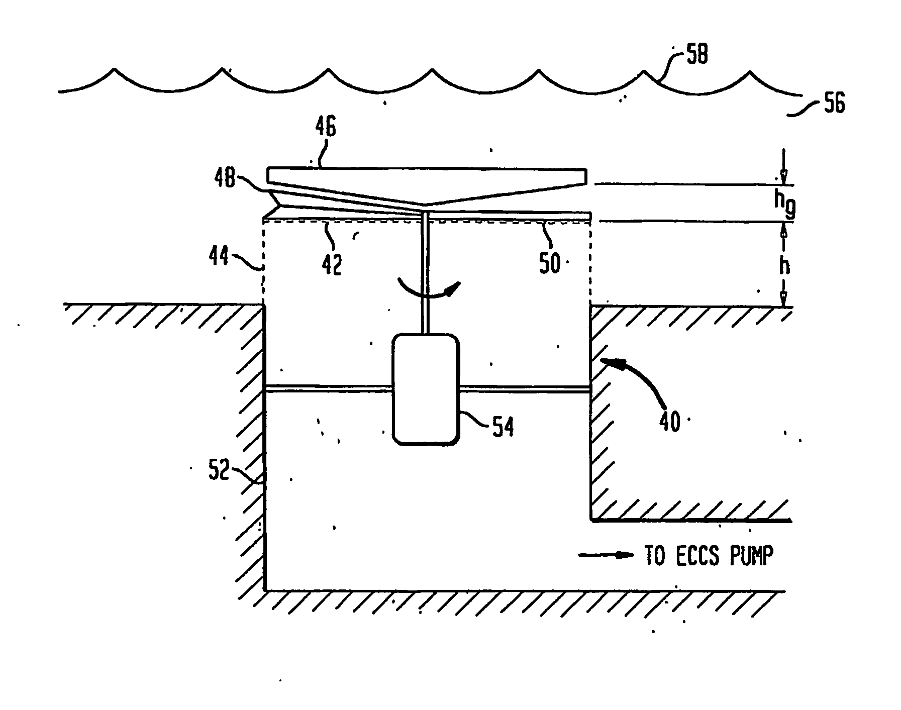
[0035]FIG. 3 shows various components of an exemplary self-cleaning strainer that can be utilized to implement the inventive concepts described herein. The self-cleaning strainer includes a top inlet mesh or screen 42, a side inlet mesh or screen 44, a combined jet or missile shield and pump end plate 46, a plow or impeller 48, a brush 50, a loop 52 and a drive motor 54.

[0036] The loop 52 and top screen 42 and side screen 44 are typical of dry PWR containments as constructed at many sites within the United States of America. The sump 52 is normally dry, so that at the start of a postulated LOCA, it may be exposed to the initial jet and missile debris predicted in such circ...


PUM

PropertyMeasurementUnit
Flow rateaaaaaaaaaa
Speedaaaaaaaaaa
Distanceaaaaaaaaaa

Abstract

An externally powered, self cleaning strainer incorporating a projectile shield, which is capable of operating for an extended period of time. A suitably shaped, motor driven, impeller creates a localized, radially outward flow of fluid in the vicinity of the strainer inlet. The projectile shield has a lower surface shaped to deflect fluid to the strainer at a constant velocity, enabling the impeller to eject debris more efficiently. Maintaining a constant flow through the strainer also avoids additional head loss associated with accelerating flow. The self cleaning strainer may also include a brush attached diametrically opposite to the impeller to aid in removing debris from the inlet side of the strainer. The impeller may also be shaped so that when it is swept past the inlet side of the strainer, it causes a localized, reverse flow through the strainer, thereby removing debris particles from within the strainer.

Description

CROSS REFERENCE TO RELATED APPLICATIONS [0001] This application is related to, and claims priority from U.S. Provisional Patent application No. 60 / 470,496 filed on May 15, 2003 by Bilanin, et al. titled ā€œImproved Self Cleaning Strainerā€, and to PCT application PCT / US04 / 14875 filed on May 13, 2004 by Bilanin, et al. titled ā€œImproved Self Cleaning Strainerā€, the contents of both of which are hereby incorporated by reference.FIELD OF THE INVENTION [0002] The invention relates generally to methods and apparatus for self-cleaning strainers, and more specifically, to improved methods, apparatus, and systems for self-cleaning strainers having reduced pressure drop and incorporating missile debris shielding. BACKGROUND OF THE INVENTION [0003] Self-cleaning, self-propelled strainers may be useful components of the emergency core cooling system (ECCS) of Boiling Water Nuclear Reactors (BWR). In the event of a Loss of Coolant Accident (LOCA), the ECCS will need to operate for extended periods ...

Claims


Application Information

Patent Timeline
05 Oct 2006
Publication
US20060219645A1
IPC
B01D29/62; B01D29/01; B01D37/00; G21C
CPC
B01D29/01; B01D2201/313; B01D29/114; B01D29/6415; B01D29/666; B01D29/86; B01D29/904; Y02E30/30
Inventors
BILANIN, ALAN J.; KAUFMAN, ANDREW E.