Brittle material fine particles with internal strain for use in aerosol deposition method

a technology of brittle material and fine particles, which is applied in the direction of transportation and packaging, coatings, chemistry apparatuses and processes, etc., can solve problems such as weak impact resistance, and achieve the effect of increasing the effect and removing the cohesion factor

Inactive Publication Date: 2006-10-05
TOTO LTD +1
View PDF9 Cites 15 Cited by
  • Summary
  • Abstract
  • Description
  • Claims
  • Application Information

AI Technical Summary

Benefits of technology

[0024] Accordingly, when a mechanical impact force is applied to these brittle materials, deformation of a crystal lattice is caused, for example, along a cleavage plane such as a boundary face of crystallites, or the brittle material is fractured. Once these phenomena are caused, atoms that initially existed inside and have bonded with other atoms appear in the deformed surface or the fracture surface. In other words, new surfaces are formed therein. One atomic layer section of this newly formed surface is forcibly exposed in an unstable state instead of a stable atomic bonding state by external force. Namely, the atomic layer section is placed in a state of high surface energy. This active surface bonds with the adjacent brittle material surface, the adjacent newly formed surface of the brittle material, or a substrate surface and becomes stable. Addition of a continuous external mechanical impact force continuously generates this phenomenon and as a result of repeated deformation, fracture or the like of fine particles, development of bonding and compactness of the structure formed by the development of bonding are effected. In this manner, the structure of the brittle material is formed.
[0086] The shredders described above can be combined to increase the effect.

Problems solved by technology

Thus, the ceramic shows strong resistance to hardness, but is weak against impact.

Method used


Image

  • Brittle material fine particles with internal strain for use in aerosol deposition method
  • Brittle material fine particles with internal strain for use in aerosol deposition method
  • Brittle material fine particles with internal strain for use in aerosol deposition method

Examples


first embodiment

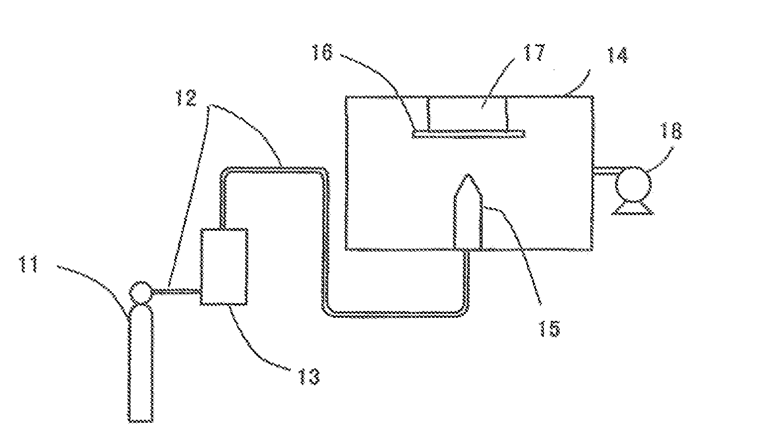
[0109]FIG. 1 is a view showing a first embodiment of a composite structure forming apparatus. A helium gas cylinder 11 is connected to an aerosol generator 13 through a carrier pipe 12 and a nozzle 15 with a rectangular opening of 5 mm×0.5 mm is disposed within a structure-forming chamber 14 through the carrier pipe. A tabular substrate 16 made of metal aluminum (Al) is mounted facing the nozzle on a substrate holder 17 which is controllable by a computer vertically (Z) and longitudinally and laterally (XY) 10 mm from the nozzle 15. The structure-forming chamber 14 is connected to an exhaust pump 18.

[0110] In the present invention, since raw fine particles with internal strain are used, a planetary grinder or a mill serving as pre-treatment equipment for imparting the internal strain to the raw fine particles is arranged next to the aerosol generator 13 or the like. However, it is also possible to convey the raw fine particles that have been pre-treated in a different location to b...

second embodiment

[0113]FIG. 3 is a view showing a second embodiment of a composite structure forming apparatus. In a composite structure forming apparatus 20, an air compressor 21 for providing compressed air is connected to an aerosol generator 23 through a carrier pipe 22. Provided on the downstream side of the aerosol generator 23 is a shredder 24 which is connected to a nozzle 25 with a rectangular opening of 10 mm×0.5 mm. Under atmospheric pressure, a substrate 27 of metal aluminum (Al) is mounted facing the nozzle 25 on a substrate holder 26 which is movable vertically (Z) and longitudinally and laterally (XY) at intervals of 2 mm from the end of the nozzle 25.

[0114]FIG. 4 is a schematic cross-sectional view of the aerosol generator 23 used in the second embodiment. An introduction section 232 connected to the carrier pipe 22 not shown in FIG. 4 is disposed on a level with a guide section 233 connected to the carrier pipe 22, not shown in the figure, relative to a container 231. Provided abov...

third embodiment

[0118]FIG. 6 is a view showing a third embodiment of a composite structure forming apparatus. A nozzle 31 of the composite structure forming apparatus 30 is connected to an aerosol generator not shown in the figure through a carrier pipe 32 made of a flexible material. The nozzle 31 is held by an end of a flexibly movable arm 34 which is controlled by a computer 33 to face a complicatedly shaped object 35 such as a substrate.

[0119] Operation of the above ceramic structure forming apparatus 30 will now be described. The ceramic ultra-fine particles are conveyed from an aerosol generator not shown in the figure through the carrier pipe 32 and ejected onto the surface of the complicatedly shaped object 35 from the nozzle 31 at high speed for deposition. The movable arm 34 is controlled by the computer 33 to trace the surface, i.e., a profile, of the complicatedly shaped object 35 to be coated by the ceramic structure moving at a fixed distance from the surface of the object. In this m...


PUM

PropertyMeasurementUnit
sizeaaaaaaaaaa
speedaaaaaaaaaa
temperatureaaaaaaaaaa

Abstract

A material composed of brittle material fine particles, such as ceramic or metalloid fine particles, for forming a composite structure on a substrate surface. The brittle material is pretreated to achieve a specific size range of fine particles and to develop a desired range of internal strain therein. The brittle material fine particles are adapted to form an aerosol with a gas stream, and when the aerosol is ejected to collide with a substrate surface, this causes collision of brittle material fine particles with a substrate surface thus imparting a mechanical impact to the fine particles. Such mechanical impact fractures or deforms the particles, and thereby generates an active new surface for brittle material fine particles after being fractured or deformed.

Description

CROSS-REFERENCE TO RELATED APPLICATION [0001] The present invention is a divisional application of co-pending U.S. patent application Ser. No. 10 / 070,104, filed on Oct. 3, 2002, which in turn is a 371 (national phase) of PCT International Serial No. PCT / JP00 / 07076 filed Oct. 12, 2000. The subject matter of these priority documents is incorporated herein by reference. BACKGROUND OF THE INVENTION [0002] 1. Field of the Invention [0003] The present invention relates to a material composed of brittle material fine particles, such as ceramic or metalloid fine particles, for forming a composite structure on a substrate surface. More particularly, the present invention relates to brittle material fine particles, having a desired range of size and internal strain, which are adapted to form an aerosol with a gas stream, and when the aerosol is ejected to collide with a substrate surface, the fine particles generate an active new surface after being fractured or deformed due to mechanical imp...

Claims


Application Information

Patent Timeline
Patent Type & Authority Applications(United States)
IPC IPC(8): B32B17/06B22F9/04C23C24/04
CPCC03C2217/282C03C2218/17C23C24/04B22F9/04B22F2009/045Y10T428/2839C03C17/22C03C17/23C03C2217/214C03C2217/268Y10T428/25C03C17/06Y10T428/31678C04B41/52
Inventor AKEDO, JUNITO, TOMOKADSUYOKOYAMA, TATSUROMORI, KATSUHIKOHATONO, HIRONORIKIYOHARA, MASAKATSUASO, YUJI
Owner TOTO LTD
Why Eureka
Try Eureka