
Closed loop fat transplantation system

Active Publication Date: 2006-10-05
LEE HEE YOUNG
View PDF16 Cites 69 Cited by
  • Summary
  • Abstract
  • Description
  • Claims
  • Application Information

AI Technical Summary

Benefits of technology

[0036] Namely, the object of the present invention is to provide a fat transplantation system, which solves the problems of mass fat transplantation such as inefficiency due to a lot of absorption, possibility of serious side effects like an infection, a lot of surgery time. Thereby it makes impossible mass fat transplantation possible and secure, also maximizes convenience of surgery.
[0038] Furthermore, the object of the present invention is to provide a fat transplantation system to use existing syringes in order to utilize the existing system simply and economically, to organize an apparatus in order to use air pressure itself which was dumped from suction vacuum pump, to utilize the most convenient means in accordance with liposuction position and transplantation amount, to utilize properly an observation / monitoring device, a check valve preventing air inflow, another check valve removing air in order to protect serious side effect like fat embolism, to minimize infection problem.
[0040] According to the present invention, the receptacle has a structure as one for fat extraction as well as pressure receptacle for fat transplantation, which is composed of a structure giving positive / negative pressure by mechanical system to improve efficiency of liposuction and fat transplantation.
[0041] With the said fat transplantation receptacle, compositions of closed loop fat transplantation system according to the present invention are a handpiece improving efficiency of liposuction, a pressure pressurization / decompression means, a centrifuge and etc. These compositions are essentially required or functioning very usefully in all process of fat transplantation; extracting a fat, treating the extracted fat, removing liquid, transplanting the fat into the body.
[0046] Moreover, handpiece is included as a composition, which is used as valuable means improving efficiency of fat extraction giving fine oscillation to cannulae during liposuction.
[0047] Each of the said compositions can perform fat transplantation without receptacle transfer using the same FT receptacle by extracting fat from patient's body giving negative pressure through the piston head to the fat storing space, transplanting the fat into the patient's other sites giving positive pressure through that. Thereby it prevents fundamentally microbe infection by air contact during the process of fat extraction and transplantation, reduces troublesome to transfer and bottle the extracted fat during transplantation, makes mass fat transplantation possible without side effects.

Problems solved by technology

Various kinds of fat aspiration and fat transplantation have been already performed, but fat transplantation has a problem that its application range is little due to many limitations.
Problems on this occasion are
1) Unless a large filter is used, fine hole of the filter gets to be clogged easily.
2) In the process of fat transfer from filter to syringe, the process became complicated and much time was required.
Consequently the frequency of air contact becomes increased, so that the possibility of contamination gets high.
3) Also loss of a plenty amount of fat is caused because much amount of tissue stuck to the filter.
4) It takes much time and it is inconvenient since hand-operated pressure is used during injection.
In order to use hand-operated injection, the piston syringe having a thick diameter can't be utilized such as a syringe for aspiration due to its big resistance when the fat passes through the needle.
Problems at this situation are
Therefore there is an inconvenience of releasing the lock and repeating again the process.
Also the process is hard and troublesome to lock the piston of syringe as pulling it.
2) User has to transfer the aspirated fat to the syringe for centrifuge / injection, so that this process is also complicated and it requires a lot of time.
At this time the fat gets to come into contact with a great quantity of air in several spaces, therefore the possibility of contamination is increased.
3) It takes much time and it is inconvenient since hand-operated pressure is used at the time of injection.
1) A problem is generated due to low injection pressure.
Pressure for fat movement through syringe needle is very large.
Therefore it takes much time, user suffers inconvenience.
First, desired cosmetic effect can't be displayed.
Second, in case of fat gathered in one place and not spread out evenly, the contacting area with recipient site becomes small in comparison with same amount of fat.
Since they can be diverted into fatal infection symptoms all over the body, mass transplantation beyond regular amount (about 100 cc or more) is difficult and actually it has been hardly carried.
2) Another serious problem is infection.
Although the fat tissue is not a necrosis, once it is separated from the body, its resistibility against germs gets extremely weak.
Therefore it is unendurable against some germs, it can be spread into infection.
Even a germ exists in the air, the more the contacting time with non-sterilized indoor air and contacting areas, the higher the possibility of infection.
However it isn't suitable in case of mass fat transplantation such as over 100 cc of lipoinjection to one site since it uses small syringes.
At present, fat transplantation is used for treating wrinkles and small depression, but mass fat transplantation enough to breast augmentation is scarcely used due to infection and low survival rate.
Although it is carried out, it is considered as impracticable since it takes a lot of time and force.
3) Hand-operated injection method can't regulate injection pressure.
If the resistance can't be perceived, injection circumstance is invisible, so that equal distribution can't be accomplished at each part.

Method used


Image

  • Closed loop fat transplantation system
  • Closed loop fat transplantation system
  • Closed loop fat transplantation system

Examples


Embodiment Construction

[0056] Now, preferred embodiments of the present invention will be described in detail with reference to the annexed drawings.

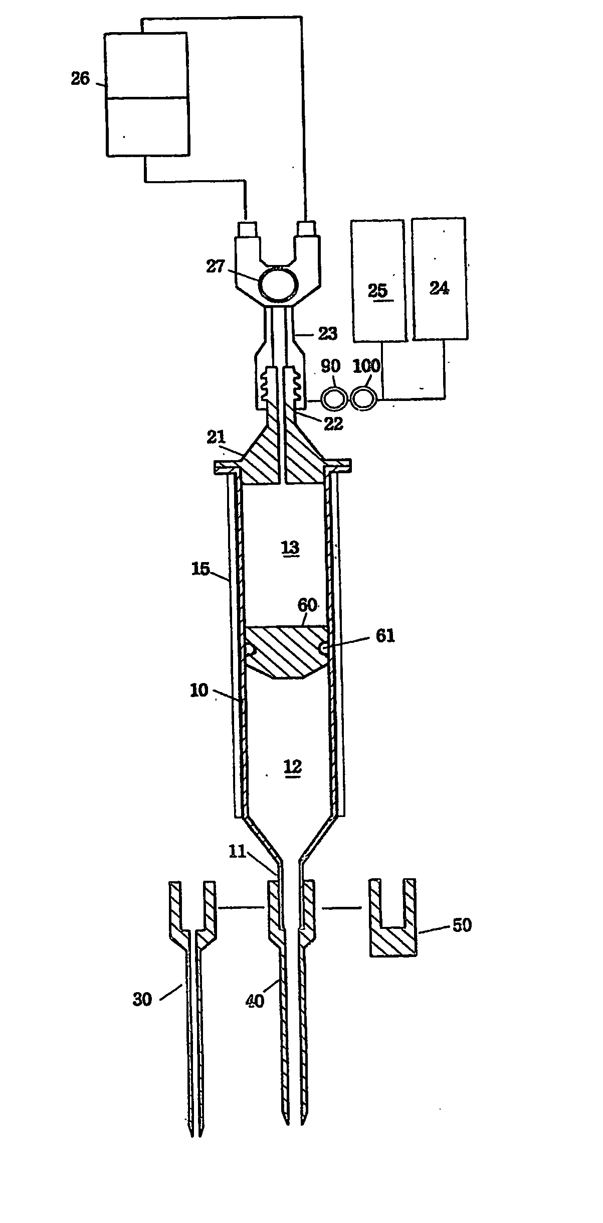
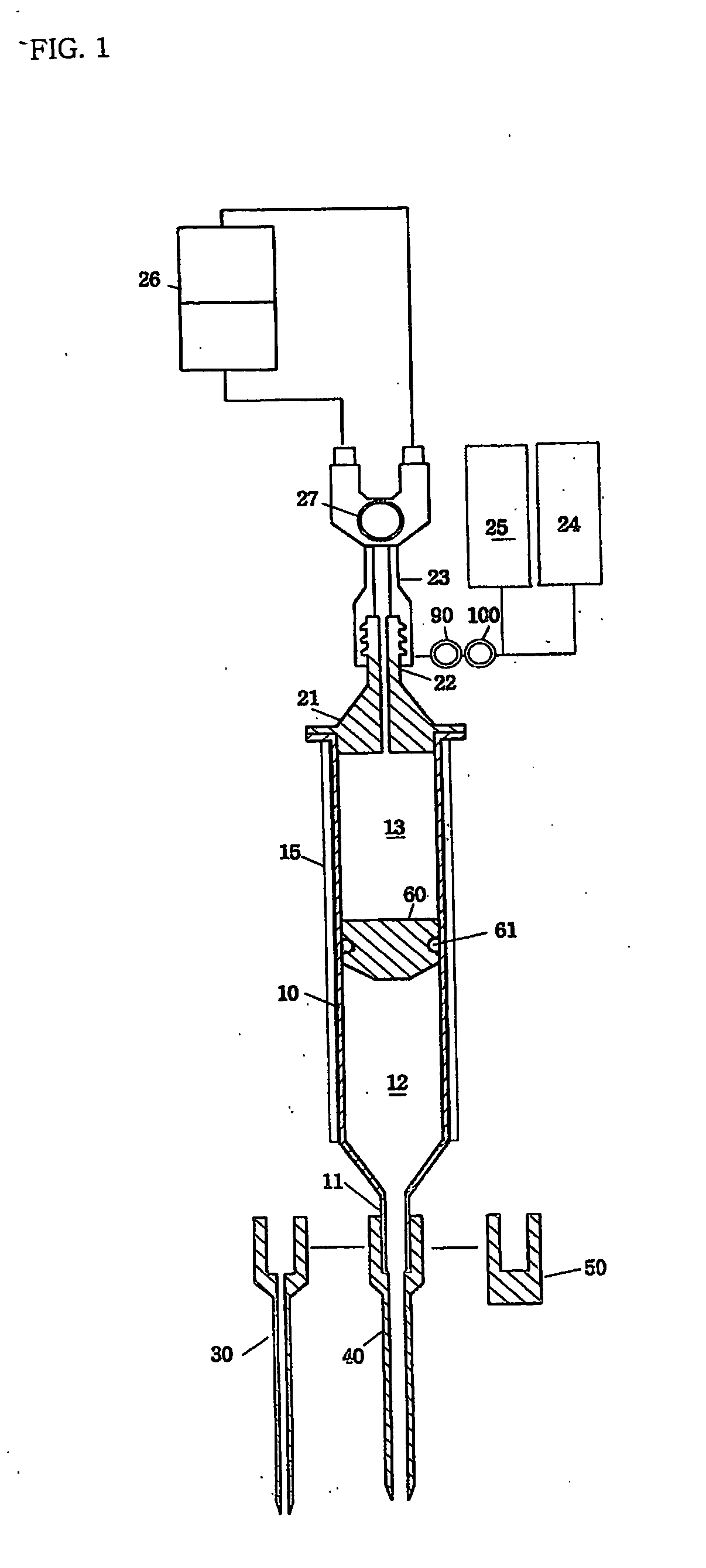
[0057]FIG. 1 illustrates a closed loop fat transplantation system in accordance with one embodiment of the present invention. The closed loop fat transplantation comprises a FT receptacle 10, a pressurization / decompression means 20 joined with each suction unit and air pressure unit.

[0058] According to the said embodiment, the FT receptacle is designed to a cylinder-shaped receptacle to attach selectively an independent syringe needle 30, a cannulae 40 or stopple 50 to its vertical hem portion 11.

[0059] Also, the said FT receptacle includes a piston head 60, which is inserted to parcel out the inside of the cylinder-shaped receptacle between front fat storing space 12 and rear pressurization / decompression space 13.

[0060] The FT receptacle has a shape similar to general disposable syringe, but it is designed for reinforce structure to operate high pressure...


PUM


Abstract

The present invention provides a closed loop fat transplantation system newly designed to aspirate a fat, to handle it without receptacle transfer and to transplant it into the human body, which is composed of a fat transplantation receptacle(hereinafter referred as FT receptacle) and an exterior mechanical pressurization / decompression means. The said FT receptacle includes a vertical hem portion where joining selectively individual syringe needle or cannelae, a cylinder-shaped receptacle to aspirate and store fat, a piston head to parcel the said cylinder-shaped receptacle into front fat storing space and rear pressurization / decompression space. The said pressurization / decompression means can give positive / negative pressure to the fat storing space through the piston head of the said FT receptacle and it has a structure separable from the said FT receptacle. Accordingly fat transplantation can be performed without receptacle transfer using the same FT receptacle extracting fat from patient's body giving negative pressure through the piston head to the fat storing space.

Description

TECHNICAL FIELD [0001] The present invention relates to a closed loop fat transplantation system, which is used when aspirating patients' fat and transplanting it into his other sites again, more particularly, the present invention comprises steps of extracting a fat from patient using a syringe-structural bidirectional receptacle which can use mechanical negative / positive pressure in the same space, disposing of the aspirated fat without receptacle transfer, transplanting it into the interior of the body. BACKGROUND ART [0002] Various kinds of fat aspiration and fat transplantation have been already performed, but fat transplantation has a problem that its application range is little due to many limitations. [0003] The process of conventional fat transplantation is as follows. [0004] The region of patient's body was small incised. A pipe(cannulae) having a hole on its distal end was inserted. Fat was aspirated through the cannulae using negative pressure. Liquid ingredients such as...

Claims


Application Information

Patent Timeline
IPC IPC(8): A61M1/00A61B17/00A61M5/00A61B17/34A61M5/145
CPCA61B17/3468A61B2017/00969A61M1/0009A61M5/1452A61M2202/08A61M5/20A61M5/2053A61M2005/3104A61M5/14526A61B2017/00792A61M2205/103A61M1/67A61M1/815A61M5/00
Inventor LEE, HEE-YOUNG
Owner LEE HEE YOUNG
Learn More