Optical element employing liquid crystal having optical isotropy

a liquid crystal and optical isotropy technology, applied in non-linear optics, instruments, static indicating devices, etc., can solve the problems of limited application of liquid crystal etalon type wavelength-variable filter, inconvenient operation, and inability to achieve accurate temperature control, etc., to achieve high-speed optical and high-speed

Inactive Publication Date: 2006-10-12
ASAHI GLASS CO LTD
View PDF4 Cites 149 Cited by
  • Summary
  • Abstract
  • Description
  • Claims
  • Application Information

AI Technical Summary

Benefits of technology

[0048] According to the present invention, since the refractive index of a liquid crystal having optical isotropy, changes depending on a voltage applied via transparent electrodes, the present invention can provide an optical element having an effect of achieving high-speed response equivalent or more than that of conventional elements, without depending on incident polarization.
[0049] Further, by employing a blue phase liquid crystal or a polymer stabilized blue phase liquid crystal, it is possible to provide a diffraction element and an optical attenuator having an effect of obtaining high-speed optical switching and extinction ratio equivalent or more than those of conventional elements, without depending on incident polarization.
[0050] Further, by

Problems solved by technology

However, since the blue phase is developed only within the above-mentioned extremely narrow temperature range, accurate and difficult temperature control is required.
However, no example of the construction of a switching element has been disclosed heretofore, which uses optical isotropy and does not depend on incident polarization state.
However, due to polarization dependence of the nematic liquid crystal, the application of the liquid crystal etalon type wavelength-variable filter has been limited.
However, if the spiral axis of the liquid crystal molecules is made to be perpendicular to the glass substrate, the liquid crystal turns into a

Method used


Image

  • Optical element employing liquid crystal having optical isotropy
  • Optical element employing liquid crystal having optical isotropy
  • Optical element employing liquid crystal having optical isotropy

Examples


first embodiment

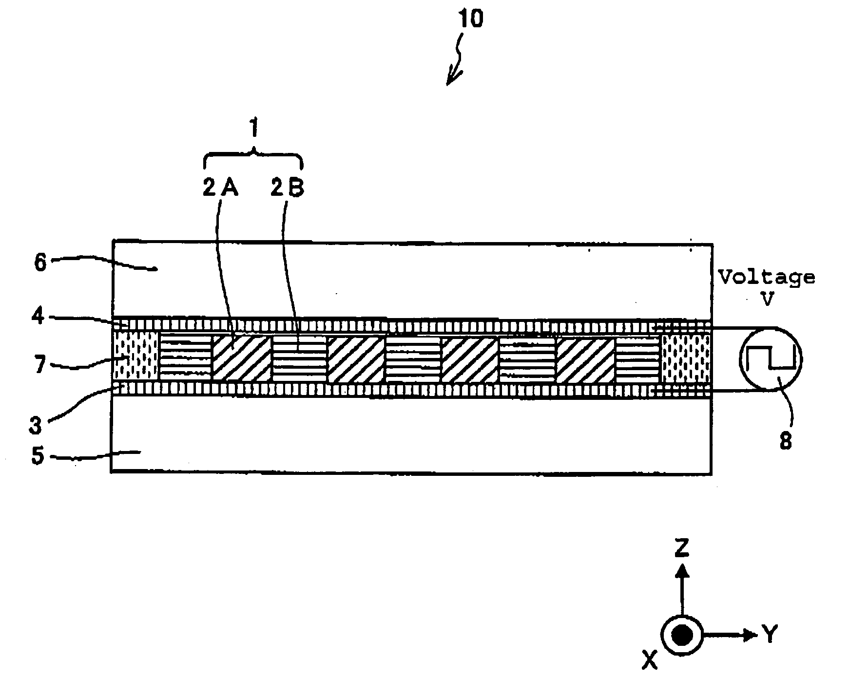
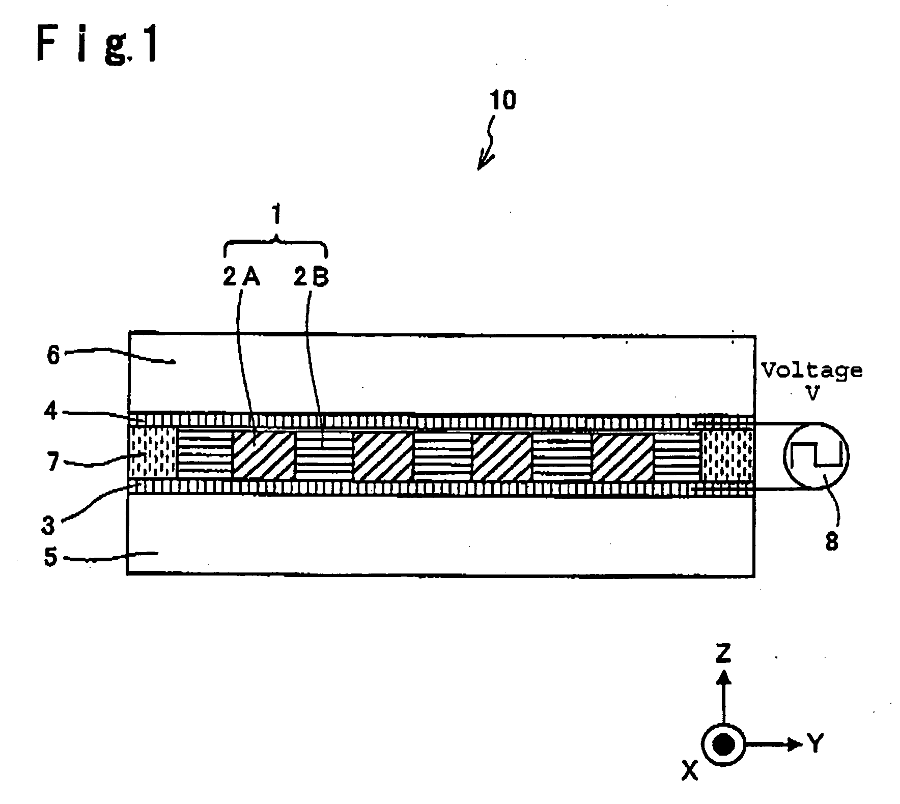
[0113] In the first embodiment of the present invention, a diffraction element and an optical attenuator are described as optical elements. FIG. 1 is a view schematically showing a cross-sectional structure of a diffraction element according to the first embodiment of the present invention. In FIG. 1, a diffraction element 10 has a construction comprising transparent substrates 5 and 6, transparent electrodes 3 and 4 formed on one surface of the transparent substrate 5 and one surface of the transparent substrate 6 respectively, a grating 2A present between the transparent electrodes 3 and 4 and constituted by isotropic-refractive-index solid material members of substantially rectangular solid shape arranged periodically in parallel with each other, a diffraction grating 1 constituted by an isotropic-refractive-index liquid crystal 2B filling regions between the isotropic-refractive-index solid material members constituting the grating 2A, and a seal 7 sealing the isotropic-refracti...

second embodiment

[0140] In the second embodiment of the present invention, an element having a construction different from that of the diffraction element and the optical attenuator according to the first embodiment of the present invention in terms of an optical element, is described. FIG. 8 is a cross-sectional view of a diffraction element according to the second embodiment of the present invention, and FIG. 9 is a plan view of the diffraction element. A diffraction element 40 according to the second embodiment of the present invention has a construction that the transparent electrode 4 is removed from the diffraction element 10 according to the first embodiment of the present invention and patterned transparent electrodes 3A and 3B are provided instead of the transparent electrode 3.

[0141] Here, the transparent electrodes 3A and 3B are formed so as to be sandwiched between the transparent substrate 5 and the grating 2A. Other portions in the construction are the same as that of the diffraction ...

third embodiment

[0148] In the third embodiment of the present invention, a wavelength-variable filter is described as an optical element. FIG. 10 is a view showing a schematic side-cross-sectional structure of a wavelength-variable filter according to the third embodiment of the present invention. In FIG. 10, a wavelength-variable filter 50 is a so-called liquid crystal etalon type wavelength-variable filter, which comprises a pair of transparent substrates 56A and 56B opposing to each other, a pair of reflective mirrors 53A and 53B disposed on the transparent substrates 56A and 56B so as to be substantially in parallel with each other and constituting an optical resonator, an isotropic-refractive-index liquid crystal 51 having a refractive index isotropically changing, and transparent electrodes 52A and 52B, and which has a construction that an isotropic-refractive-index liquid crystal 51 and a layer 58 (hereinafter referred to as solid optical medium layer) of transparent and solid, are sandwiche...


PUM


Abstract

An optical element is provided, which can realize high speed response equivalent or more than that of conventional elements without depending on incident polarization.
A diffraction element 10 comprises transparent substrates 5 and 6, a grating 2A made of an isotropic refractive index solid material formed on the transparent substrate 5 and having a cross-sectional structure having a periodical concavo-convex shape, a blue phase liquid crystal 2B which fills the concave portions of grating 2A including a periodical concave-convex shape having a refractive index which changes isotropically, and transparent electrodes 3 and 4 for applying voltage to the blue phase liquid crystal 2B, wherein the grating 2A and the blue phase liquid crystal 2B constitutes a diffraction grating 1, and the diffraction element 10 has a construction that the refractive index of the blue phase liquid crystal 2B is changed by the voltage applied via the transparent electrodes 3 and 4.

Description

TECHNICAL FIELD [0001] The present invention relates to an optical element employing a liquid crystal having optical isotropy, in particular, to a diffraction element and an optical attenuator employing the above liquid crystal as a part of diffraction grating, which is adapted to apply voltage to control substantial refractive index of the liquid crystal, and diffracts incident light to control light quantity of 0-th order diffraction light (transmitted light), a wavelength-variable filter and a wavefront control element for taking out selectively and variably light signal having a desired wavelength from a light signal having multiple wavelengths, a liquid crystal lens which shows a lens effect by controlling the effective refractive index of the liquid crystal employed in the wavefront control element, and an aberration correction element for compensating a wavefront aberration of an optical system by changing a wavefront of output light with respect to that of input light. BACKG...

Claims


Application Information

Patent Timeline
IPC IPC(8): G02F1/13G02F1/133G02F1/137G02F1/19
CPCG02F1/13306G02F1/134363G02F1/13718G02F2203/18G02F2001/13793G02F2001/294G02F2203/06G02F1/19G02F1/133371G02F1/13793G02F1/294G02F1/13G02F1/137
Inventor OOI, YOSHIHARUNOMURA, TAKUJIKOYANAGI, ATSUSHI
Owner ASAHI GLASS CO LTD
Why Eureka
Try Eureka