
Method and system for treating sludge

a technology of sludge and treatment method, which is applied in water/sludge/sewage treatment, water treatment parameter control, lighting and heating apparatus, etc. it can solve the problems of limited pump capacity, inability to feed sludge, and inability to handle sludge in connection with sewage treatment plants, so as to improve heat conductivity, improve heat transfer in heat exchanger to sludge, and improve the effect of heat conductivity

Inactive Publication Date: 2006-10-26
PURAC
View PDF0 Cites 12 Cited by
  • Summary
  • Abstract
  • Description
  • Claims
  • Application Information

AI Technical Summary

Benefits of technology

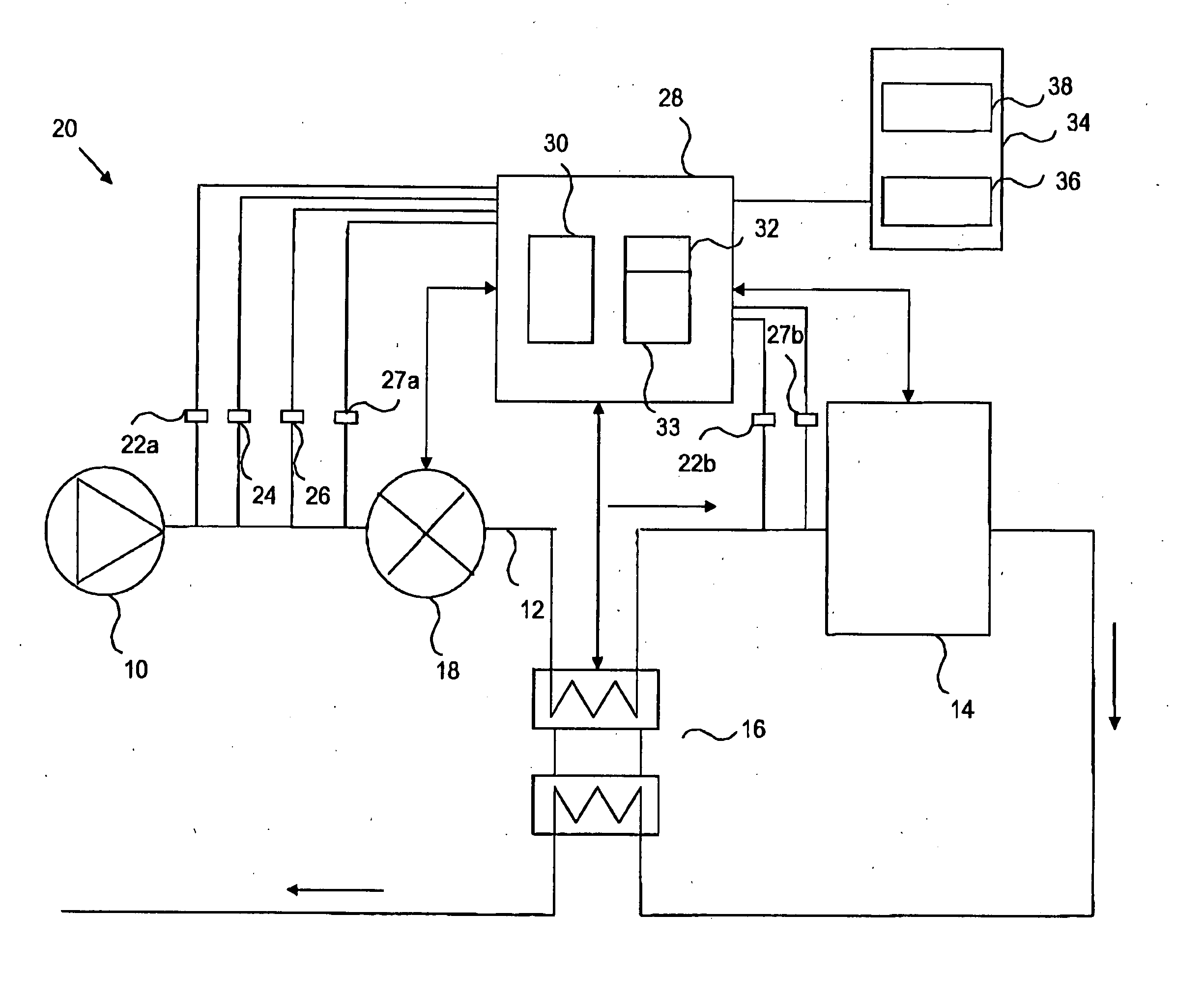
[0013] An advantage of the present invention is that the heat transfer in the heat exchanger to the sludge can be improved since a lower viscosity of the sludge entails improved heat conducting properties between the warm surfaces of the heat exchanger and the sludge. Thereby, the heat transfer and the efficiency of the heat exchanger can be improved, which, in turn, affects the overall energy consumption of the system in a positive way. Moreover, the benefits of the present invention are also in that it facilitates the pumping of sludge since the viscosity is decreased. On the other hand this enables the pumping of sludge with a higher dry content than was previously feasible for the same pump capacity. This also contributes to a reduced energy consumption of the system. Moreover, the use of primary energy in the system can be reduced since energy can be recovered from a heat exchanger.
[0014] The reliability of the system is also improved due to the decreased viscosity.
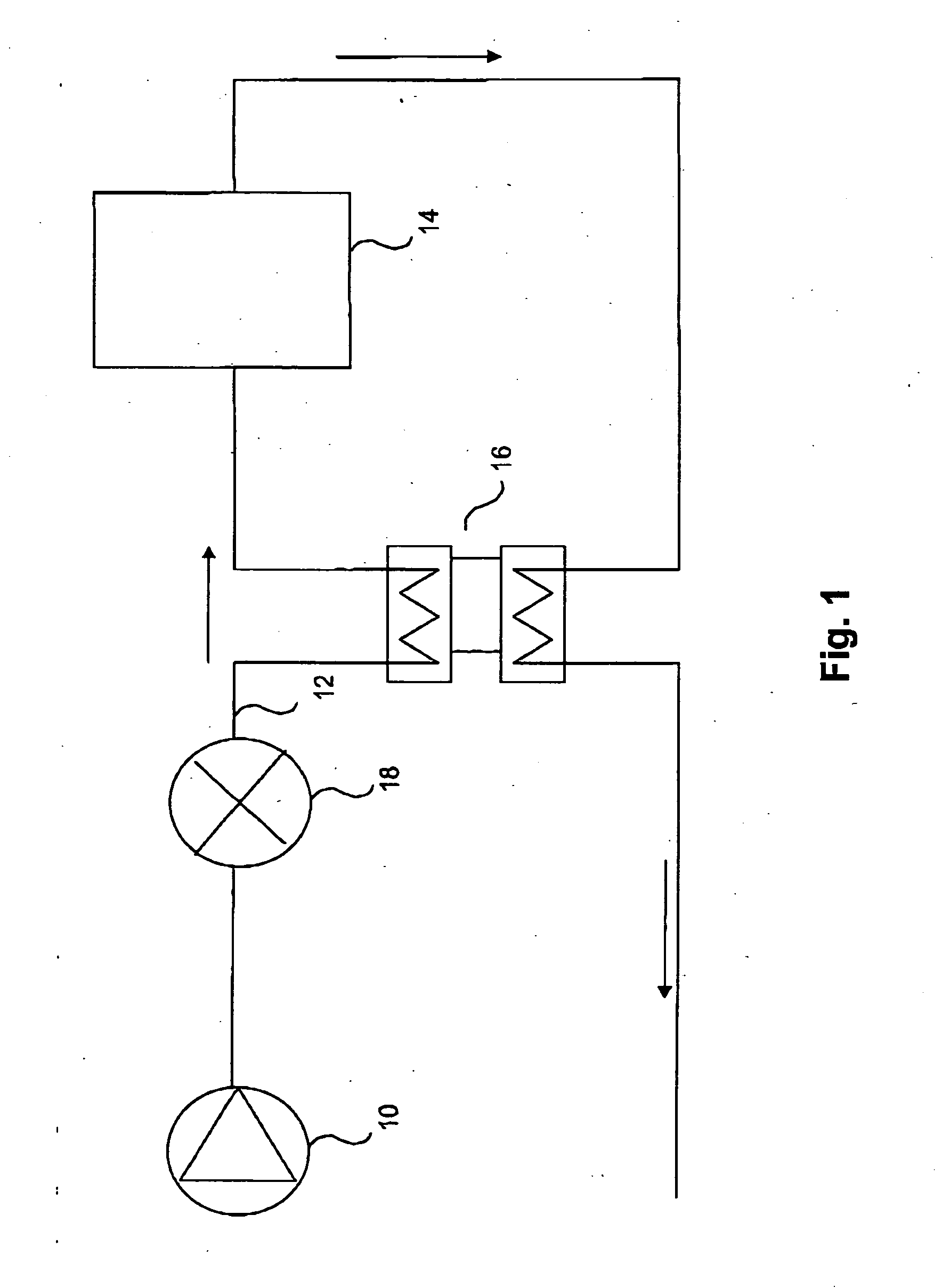
[0015] For applications handling sludge from a sewage treatment plant the sludge is fed to a digester. The sludge having decreased viscosity may then be fed through a heat exchanger for heating the sludge with the aid of a pump and decreasing the viscosity of the sludge in the vicinity of the pump.
[0016] For treatment of sludge from sewage treating plants, this means that the treatment process of the sludge in e.g. digesters is promoted because the stabilizing process in the digester is favoured by a higher dry content.
[0017] The combination of a pump and a viscosity decreasing means can be applied in many locations in a sludge treating system, such as up-streams a heat exchanger, in a sludge circulation and heating circuit connected to the digester, and for feeding the treated sludge to an outlet of the system.
[0018] According to preferred embodiments of the present invention, control means can be arranged to control the function of the pump, the viscosity decreasing means, and the heat exchanger by using different operating parameters and properties of the sludge. For example, the viscosity decreasing means can be controlled as a function of the pressure, energy optimization, flow and temperature of the sludge, and the composition of the sludge. The heat exchanger may be controlled as a function of the flow of the sludge.

Problems solved by technology

Handling and treatment of sludge in connection with sewage treatment plants is a major issue for planning and running such a plant.
The treated sludge that is taken out of the digester has an increased temperature, and if the temperature is not lowered the biological process continues, which is unfavourable.
However, since the viscosity of the sludge increases with the dry content the feeding of the sludge is limited to what the pumps are able to handle.
Alternatively, larger pumps have to be used in order to pump the thickened sludge, which, inter alia, increases the energy consumption.
The problem increases when the sludge is to be fed through heat exchangers during its treatment since a higher viscosity of the sludge entails impaired heat conducting properties between the warm surfaces of the heat exchanger and the sludge.
This problem has with new thickening techniques such as polymer addition to the sludge.

Method used


Image

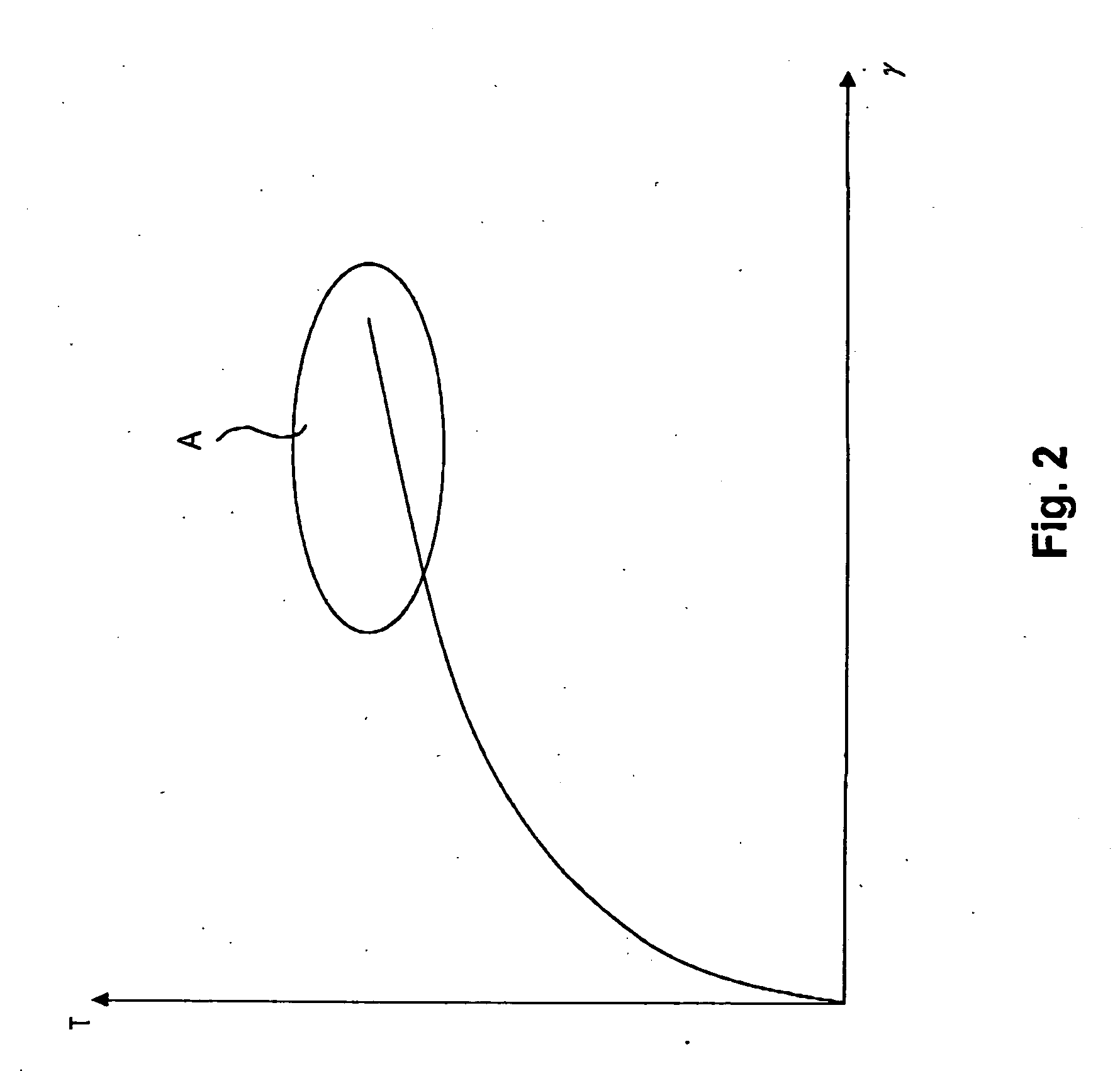
  • Method and system for treating sludge
  • Method and system for treating sludge
  • Method and system for treating sludge

Examples


Embodiment Construction

[0030] The general aim of the present invention is to facilitate the transport and handling of sludge and other materials displaying similar properties.

[0031] Sludge has in general a high viscosity, which is increased with the dry content of the sludge and with the polymer content. This creates a problem when handling sludge in a sewage treatment plant for instance. One important aspect and goal when handling waste water is to reduce the water content as much as possible from the sludge before treating the sludge, a biological, chemical of thermal stabilization of the sludge, in order to reduce the odours from the sludge but also reduce the weight and volume.

[0032] The dewatering can be done by different techniques such as centrifugation, pressing or vacuum. The dewatered sludge should then be fed to be stabilized, where the feeding is done by pumps 10.

[0033] In order to facilitate the feeding of the sludge with higher dry content ratios, the present invention proposes the follow...


PUM

PropertyMeasurementUnit
temperaturesaaaaaaaaaa

Abstract

The present invention relates to a method of treating sludge in a system comprising a pump (10) having an inlet and an outlet connectable to a sludge feeding line (12) being connectable to a heat exchanger (16), comprising the steps of: feeding sludge with the aid of the pump (10); decreasing the viscosity of the sludge in the vicinity of the heat exchanger (16) in a viscosity decreasing device (18); and passing the sludge having decreased viscosity through the heat exchanger (16) for heating the sludge. The invention further relates to a system for treating sludge a computer program (33) for a control means (28) of the system of treating sludge, and a computer program product comprising computer readable medium (32) and the computer program (33). The decreased viscosity of the sludge provides for an improved heat transfer in the heat exchanger and thereby a process and energy efficient way of heating sludge.

Description

TECHNICAL FIELD [0001] The present invention relates to treatment of sludge obtained from, for example, sewage treatment plants, and, in particular, to a method and system for treating sludge that has a high dry substance content in a process and energy efficient way. BACKGROUND OF THE INVENTION [0002] Handling and treatment of sludge in connection with sewage treatment plants is a major issue for planning and running such a plant. The sludge that is obtained during the sewage treatment process has to be treated in suitable ways. [0003] Commonly the sludge is thickened and then fed by a pump 10 in a sludge feeding line 12 to a digester 14 for treating the sludge, FIG. 1. The digesters usually work with different specific temperatures, commonly 37 or 55° C. Because the incoming sludge after the de-thickening may be in the range 8-15° C., it is advantageous to recover heat from the outgoing sludge for pre-heating the incoming sludge, which may be performed by means of a heat-exchanger...

Claims


Application Information

Patent Timeline
Patent Type & Authority Applications(United States)
IPC IPC(8): C02F11/00
CPCC02F11/12C02F2209/005F26B2200/18F26B1/005C02F2209/006
Inventor GOTTHARDSSON, SOREN
Owner PURAC
Learn More