Laser welding method and laser welding apparatus

a laser welding and laser welding technology, applied in laser beam welding apparatus, welding/soldering/cutting articles, manufacturing tools, etc., can solve the problems of poor optical coupling characteristic of fundamental wavelength (e.g., 1064 nm) yag laser light with respect to copper and gold, low absorption efficiency of laser energy, etc., to achieve the effect of improving reproducibility and quality

Active Publication Date: 2006-10-26
MIYACHI TECHNOS CORP
View PDF17 Cites 30 Cited by
  • Summary
  • Abstract
  • Description
  • Claims
  • Application Information

AI Technical Summary

Benefits of technology

[0012] In a preferred embodiment of the laser welding apparatus of the present invention, a first optical fiber that transmits the YAG fundamental pulse laser light from the first laser oscillator to the laser emission unit and a second optical fiber that transmits the YAG harmonic pulse laser light from the second laser oscillator to the laser emission unit are used, and the first optical fiber for the YAG fundamental has a core diameter that is slightly larger than (preferably 1.3 times to 2 times) the core diameter of the second optical fiber for the YAG harmonic. According to this configuration, the irradiation diameter of the Y

Problems solved by technology

If the optical coupling characteristic is not good, the reflectance is high, the absorption efficiency of the laser energy is low, and it is difficult to obtain a good welding connection.
In this respect, the optical coupling characteristic of fundamental wavelength (e.g., 1064 nm) YAG laser light is not good with respect to copper and gold.
However, this conventional laser we

Method used


Image

  • Laser welding method and laser welding apparatus
  • Laser welding method and laser welding apparatus
  • Laser welding method and laser welding apparatus

Examples


Embodiment Construction

[0032] A preferred embodiment of the present invention will be described below with reference to the attached drawings.

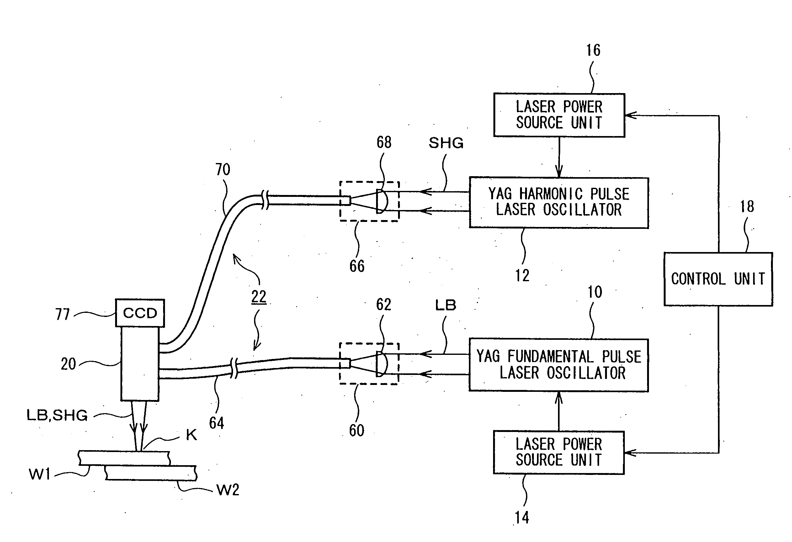
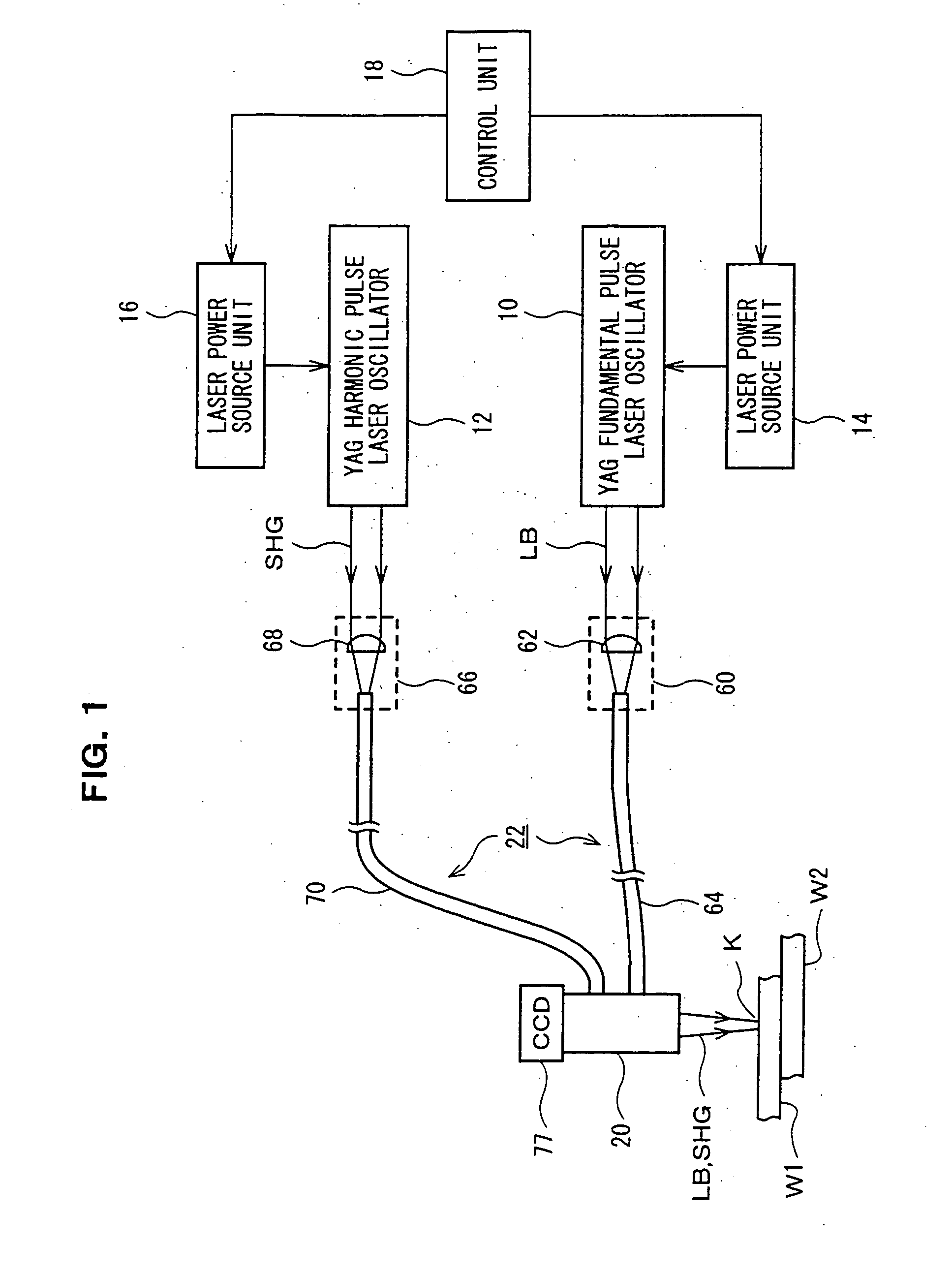
[0033]FIG. 1 shows the configuration of a laser welding apparatus that superposes two wavelengths according to the embodiment of the present invention. The laser welding apparatus includes: two YAG pulse laser oscillators 10 and 12; laser power source units 14 and 16 that are electrically connected to the pulse laser oscillators 10 and 12, respectively; a control unit 18 that controls the laser oscillation operation of both the pulse laser oscillators 10 and 12 through the laser power source units 14 and 16; an emission unit 20 that superposes two wavelengths and is disposed in a desired processing place; and an optical fiber transmission system 22 that transmits the YAG pulse laser light generated by both the pulse laser oscillators 10 and 12 respectively to the emission unit 20.

[0034] Here, the YAG pulse laser oscillator 10 oscillates / outputs pulse laser light L...


PUM

PropertyMeasurementUnit
Fractionaaaaaaaaaa
Fractionaaaaaaaaaa
Timeaaaaaaaaaa

Abstract

A YAG pulse laser oscillator 10 oscillates/outputs pulse width-variable YAG fundamental pulse laser light LB, and a YAG pulse laser oscillator 12 oscillates/outputs pulse width-variable YAG second harmonic pulse laser light SHG. An emission unit 20 superposes the pulse laser light LB and the pulse laser light SHG on the same optical axis and focuses, and irradiates a welding point K on welding pieces (W1 and W2) with, the pulse laser light LB and the pulse laser light SHG. A control unit 18 controls the laser oscillation operation of the laser oscillators 10 and 12 so that the point in time when the laser output of the YAG second harmonic pulse laser light SHG reaches its peak is slightly earlier than the point in time when the laser output of the YAG fundamental pulse laser light LB reaches its peak.

Description

BACKGROUND OF THE INVENTION [0001] 1. Field of the Invention [0002] The present invention relates to laser welding technology that welds metal using lasers, and in particular to a laser welding method and apparatus that superpose, and irradiate welding pieces with, laser beams of two wavelengths. [0003] 2. Description of the Related Art [0004] In recent years, lasers have been used in the manufacturing industry, and particularly in the fields of welding, cutting, and surface treatment. The importance of laser welding technology is actually increasing more and more because high-precision and high-speed processing can be realized, the thermal strain on the work pieces is small, and high-speed automatization is possible. At present, the solid-state laser most often used in laser welding is a YAG laser that generates a light beam with a wavelength of about 1 μm. A YAG laser is a laser where YAG (Y3Al5O12) crystal serving as the mother material is doped with rare-earth active ions (Nd3+,...

Claims


Application Information

Patent Timeline
IPC IPC(8): B23K26/20
CPCB23K26/0604B23K2203/12B23K26/0613B23K2103/12B23K26/21B23K26/02
Inventor NAGASHIMA, TAKAHIROKASE, JUNPEI
Owner MIYACHI TECHNOS CORP
Why Eureka
Try Eureka