Guide catheters for accessing cardiac sites

a catheter and guide technology, applied in the field of bilumen guide catheters, can solve the problems of difficult to aim the distal fixation mechanism toward myocardial tissue, lack of pushability, and lack of column strength, so as to achieve sufficient column strength and simplify the introduction of cardiac leads.

Inactive Publication Date: 2006-11-02
MEDTRONIC INC
View PDF30 Cites 67 Cited by
  • Summary
  • Abstract
  • Description
  • Claims
  • Application Information

AI Technical Summary

Benefits of technology

[0009] At least a portion of the guide catheter is shaped to preferentially urge the delivery catheter lumen exit port toward the vessel wall and the underlying heart and away from the pericardium and pericardial space during advancement of the guide catheter body through coronary vessels. For example, the guide catheter body is shaped in one or more segment thereof such that the delivery lumen exit port is oriented or biased inward toward the myocardium and not outward toward the pericardial sac or pericardium as the guide catheter is advanced through a coronary blood vessel that extends over the epicardium of the heart. This orientation of the delivery lumen exit port enables advancement of an active fixation mechanism of a cardiac lead out of the delivery lumen exit port and through the vessel wall and epicardium into the myocardium. The guide tool can be retracted through the guide lumen before or after advancement and fixation of the active fixation mechanism, and the guide catheter can then be withdrawn over the lead body without disturbing the fixation.
[0013] In certain embodiments, the guide catheter body is reduced in diameter in the distal portion extending between the delivery lumen exit port and the guide lumen exit port and at the catheter body distal end, also referred to herein as a “distal leader”. Consequently, the small diameter distal leader can be advanced readily over a guide wire inserted into the guide lumen through twists and turns of the tortuous pathway and thereby guides the advancement of the larger diameter proximal segment of the catheter body. The small diameter distal leader can also be advanced deeply into narrow pathways or passages to dispose the more proximal delivery lumen exit port at a desired implantation site.
[0015] The guide catheters and methods of the present invention advantageously simplify introduction of cardiac leads that lack a lumen for receiving a stiffening stylet and lack sufficient column strength to be pushed to a desired implantation site. The implantation sites include any selected implantation sites of the coronary sinus and the cardiac veins descending from the coronary sinus accessed through a transvenous pathway.

Problems solved by technology

The lead bodies of such small diameter endocardial screw-in leads are so supple and flexible that it is difficult to rotate the lead distal end by application of rotary torque to the lead proximal end unless the lead body remains relatively straight and not confined by contact with vessel walls.
This diminished “torqueability” prevents the rotation of the fixation helix at the lead distal end or renders the rotation unreliable once the lead body is advanced through a tortuous pathway and confined by contact against the vessel walls.
In addition, such lead bodies also possess little if any column strength and lack “pushability”, that is the ability to advance the lead distal end axially when the lead proximal end is pushed axially, particularly when the lead body extends through the tortuous transvenous pathway.
Once the implantation site is reached in coronary vasculature, it is difficult to aim the distal fixation mechanism toward myocardial tissue, and the fixation mechanism may inadvertently be aimed at and deployed outside the myocardium.
The pace / sense electrodes may not be in intimate contact with excitable cardiac tissue, resulting in unduly high stimulation thresholds and diminished sensing.
Fixation may be achieved temporarily, but fixation may be lost over time resulting in dislodgement of the pace / sense electrode(s).
The fixation mechanism may perforate through a coronary vessel wall into the pericardial space resulting in perforation of the vessel.

Method used


Image

  • Guide catheters for accessing cardiac sites
  • Guide catheters for accessing cardiac sites
  • Guide catheters for accessing cardiac sites

Examples


Embodiment Construction

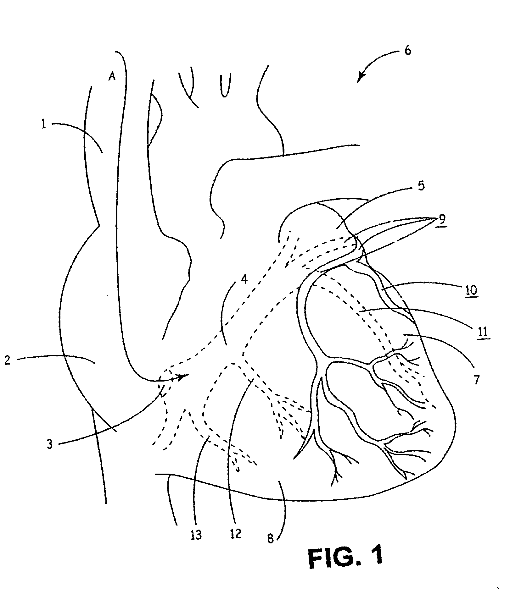
[0033] In the following detailed description, references are made to illustrative embodiments for carrying out the invention. It is understood that other embodiments may be utilized without departing from the scope of the invention. The invention and its preferred embodiments may be employed in implantation of unipolar, bipolar or multi-polar, endocardial, cardiac pacing leads, cardioversion / defibrillation leads or monitoring leads having one or more pace / sense electrode(s) or sense electrode(s), respectively, at or adjacent the distal lead end and an active fixation mechanism that is to be affixed into the myocardium. Moreover, other sensors for sensing a physiologic parameter may be incorporated into the lead body. An insulated electrical conductor extending proximally through the lead body to connector element of a lead proximal end connector assembly is coupled to each such pace / sense electrode, sense electrode, cardioversion / defibrillation electrode and sensor. The proximal con...


PUM


Abstract

Guide catheters and methods of using same for facilitating implantation of cardiac leads for applying electrical stimulation to and / or sensing electrical activity of the heart through one or more electrode positioned at an implantation site within a heart chamber or cardiac vessel adjacent a heart chamber and more particularly to a method and apparatus for introducing such a cardiac lead having low torqueability and pushability through a pathway to enable attachment of the cardiac lead at the implantation site are disclosed. The catheter body comprises delivery lumen to introduce a small diameter cardiac lead and a guide lumen to receive a guide tool to locate the catheter body distal end at the implantation site. The small diameter lumen within a small diameter guide tube extends distally from the delivery exit port of the delivery lumen. The catheter body is shaped to bias the delivery lumen exit port toward the heart.

Description

TECHNICAL FIELD [0001] The present invention relates to bilumen guide catheters for introduction and implantation of cardiac leads for applying electrical stimulation to and / or sensing electrical activity of the heart or the introduction of other medical instruments and materials into cardiac vessels, particularly the coronary sinus (CS) and vessels branching therefrom. BACKGROUND [0002] Implantable permanent and temporary medical electrical stimulation and / or sensing leads are well known in the fields of cardiac stimulation and monitoring, including cardiac pacing and cardioversion / defibrillation, and in other fields of electrical stimulation or monitoring of electrical signals or other physiologic parameters. In the field of cardiac stimulation and monitoring, the electrodes of epicardial or endocardial cardiac leads are affixed against the epicardium or endocardium, respectively, or inserted therethrough into the underlying myocardium of the heart wall. [0003] It has become possi...

Claims


Application Information

Patent Timeline
Patent Type & Authority Applications(United States)
IPC IPC(8): A61N1/05
CPCA61M2025/0037A61M2025/004A61N2001/0585A61N1/0573A61N1/057
Inventor SEIFERT, KEVIN R.
Owner MEDTRONIC INC
Why Eureka
Try Eureka