
Optimizing maldi mass spectrometer operation by sample plate image analysis

a mass spectrometer and sample plate technology, applied in the field of mass spectrometers, can solve the problems of incomplete time attention, poor data quality or significantly extended analysis, and inability to accurately measure the intensity of the sample plate, so as to improve performance and improve data acquisition efficiency.

Inactive Publication Date: 2006-11-02
THERMO FINNIGAN
View PDF14 Cites 25 Cited by
  • Summary
  • Abstract
  • Description
  • Claims
  • Application Information

AI Technical Summary

Benefits of technology

The patent describes a method and apparatus for analyzing images of sample spots on a sample plate in a mass spectrometer. The method involves capturing an image of the sample area and using a dynamic threshold value to identify regions with desired image characteristics, such as brightness or color. The image analysis technique combines the use of an auto-spectrum filtering technique to improve data acquisition efficiency. The apparatus includes a laser for irradiating a region of the sample spot and a processing unit for analyzing the image and determining which regions to irradiate based on the threshold value. The technical effects of the patent include improved accuracy and efficiency in identifying regions of the sample plate with desired characteristics and optimizing mass spectrometer performance.

Problems solved by technology

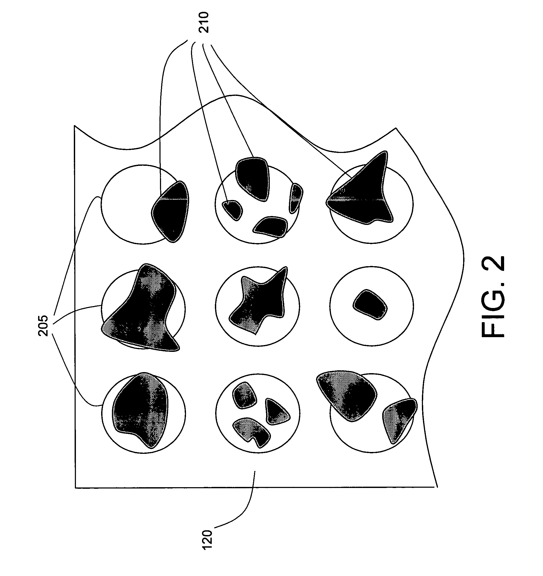
There may also be errors in the positioning of the sample spot at the target region arising from malfunction or operational limitations of the automated deposition apparatus that result in samples that are offset from the center of the target area.
Manually selecting regions within the target area typically requires the full time attention of a skilled operator and is generally not amenable to automation.
Automatically moving the laser focal point or the sample plate so that the laser beam focuses on predefined regions within in the sample spot can lead to data sets where the laser pulse has missed the sample completely due to inhomogeneity of the sample spot within the target region.
This can result in poor data quality or significantly extended analysis times as the number of laser shots for each target area is increased to ensure that adequate data is acquired.

Method used


Image

  • Optimizing maldi mass spectrometer operation by sample plate image analysis
  • Optimizing maldi mass spectrometer operation by sample plate image analysis
  • Optimizing maldi mass spectrometer operation by sample plate image analysis

Examples


Embodiment Construction

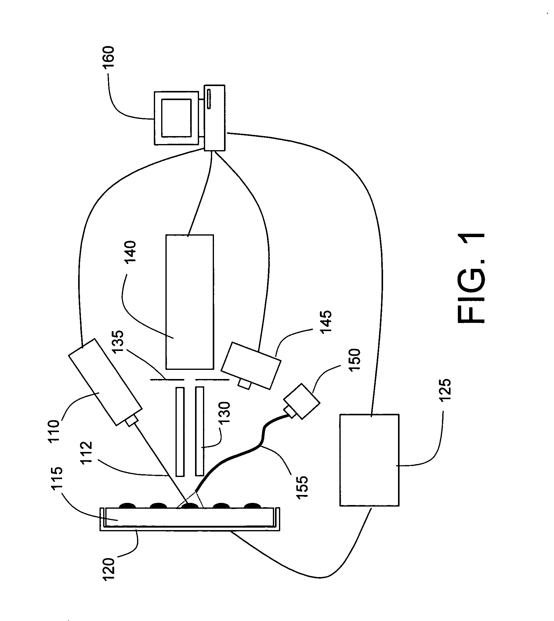
[0025] An overall configuration of a mass spectrometer (MS) system 100 according to one aspect of the present invention is illustrated schematically in FIG. 1. As shown, MS system 100 includes a laser 110 positioned to direct a pulsed beam of radiation 112 onto a sample spot deposited on sample plate 115. A sample plate holder 120 is provided with a positioning mechanism, such as an X-Y stage, to align the laser spot (the impingement area of the laser beam) with a selected region of sample plate 115. Sample plate holder 120 is typically positioned in the X-Y plane (the plane defined by sample plate 115) by means of stepper motors or similar actuators, the operation of which is precisely controlled by signals transmitted from controller 125. In alternate configurations, alignment of the laser spot with a selected region of sample plate 115 may be achieved by maintaining the sample plate 115 stationary and steering laser beam 112 by moving the laser or mirrors or other optical element...


PUM


Abstract

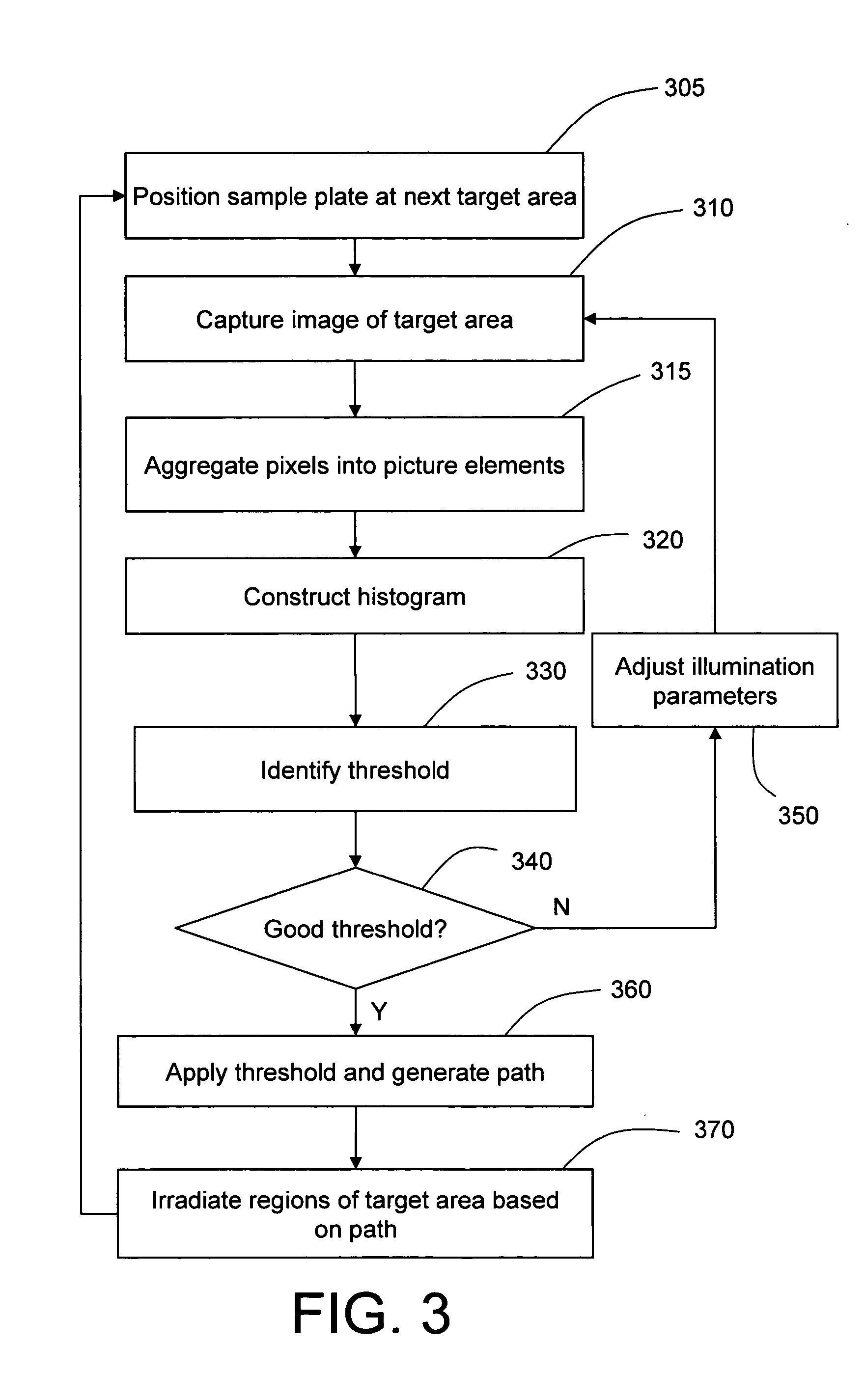
A method and apparatus are described for performing image analysis of a sample target area on a MALDI sample plate to select laser impingement locations for optimal mass spectra acquisition. The target area image is captured and analyzed to determine the incidence distribution of picture element values (representative of luminance and / or chrominance information). A dynamic threshold value may be determined by constructing a virtual histogram and then identifying a value at which a local minimum occurs between modes of a bimodal distribution. The threshold value is applied to the picture elements to locate regions within the target area that possess desired visual characteristics, such as a high luminance indicative of a crystalline structure. Mass spectra acquisition may be optimized by directing the laser beam to impinge at only those regions that possess the desired visual characteristic. The mass spectrometer performance may be further improved by coupling the image analysis process to an auto-spectrum filtering technique, whereby the laser beam is selectively held at or moved from a region of the sample spot based on whether the resultant mass spectrum meets predetermined performance criteria.

Description

BACKGROUND OF THE INVENTION [0001] 1. Field of the Invention [0002] The present invention is related to mass spectrometers, and more specifically to MALDI mass spectrometers and methods for operating the same. [0003] 2. Description of the Prior Art [0004] In recent years, matrix assisted laser desorption / ionization (MALDI) mass spectrometry, a technique that provides minimal fragmentation and high sensitivity for the analysis of a wide variety of fragile and non-volatile compounds, has become widely used. The MALDI technique may be combined with a variety of mass analyzers, such as time-of-flight (TOF) analyzers, Fourier Transform / Inductive Coupled Resonance (FTICR) analyzers, quadrupole ion traps, and single or triple quadrupoles, to provide for detection of large molecular masses. The MALDI technique may be used to determine molecular weights of biomolecules and their fragment ions, monitor bioreactions, detect post-translational modifications, and perform protein and oligonucleot...

Claims


Application Information

Patent Timeline
Patent Type & Authority Applications(United States)
IPC IPC(8): G06F19/00G06K9/00
CPCG06T7/0004G06T7/0081H01J49/164G06T2207/30108H01J49/0004G06T2207/20148G06T7/11G06T7/136G06T5/40H01J49/161
Inventor BUI, HUY A.
Owner THERMO FINNIGAN
Learn More