
Biofuel cell

a biofuel cell and biofuel technology, applied in the field of biofuel cells, can solve the problems of redox fuel cells, inability to achieve wide use, and reduced oxidant reoxidation efficiency, etc., and achieve the effect of facilitating growth

Inactive Publication Date: 2006-11-09
UNIV OF WESTERN ONTARIO
View PDF9 Cites 40 Cited by
  • Summary
  • Abstract
  • Description
  • Claims
  • Application Information

AI Technical Summary

Benefits of technology

The present invention provides a redox fuel cell with an efficient method for oxidant regeneration and the consumption of CO2. The fuel cell includes a cathode compartment containing a cathode electrode with a redox couple (Fe2+ / Fe3+), chemolithotrophic microorganisms being immobilized on the Fe2+ / Fe3+, and a pump for pumping a fluid containing oxygen and carbon dioxide into the cathode compartment. The membrane permeable to protons allows protons to cross from the cathode compartment to the anode compartment where they are oxidized by the microorganisms to ferric ions (Fe3+) in an aerobic oxidation reaction. The ferrous ions are then reduced back to Fe2+ by the chemical reduction of ferric ions in a reaction given by 4Fe3++4e-=4Fe2++2H2O. The membrane permeable to protons allows the protons to cross from the cathode compartment to the anode compartment where they are oxidized by the microorganisms to ferric ions (Fe3+) in an aerobic oxidation reaction. The system also includes a bioreactor containing chemolithotrophic microorganisms immobilized on the cathode electrode, an aqueous solution containing no iron, and a pump for pumping a fluid containing oxygen and carbon dioxide into the cathode compartment. The invention provides a more efficient method for oxidant regeneration and CO2 consumption in a redox fuel cell system.

Problems solved by technology

While there have been significant advances towards the application of fuel cells in everyday life, their widespread use has not been achieved yet due in part to the high cost of electricity they produce, see Rose, R., Fuel Cells and Hydrogen: The Path Forward, Report Prepared for the Senate of the USA, http: / / www.fuelcellpath.org.
However, the main problem in redox fuel cells is the efficiency of reoxidation of the reduced form of the oxidant (oxidant regeneration), see Larsson, R. and B. Folkesson, J. Appl. Electrochem., 20, 907 (1990); and Kummer, J. T. and D.-G.

Method used


Image

  • Biofuel cell
  • Biofuel cell
  • Biofuel cell

Examples


Embodiment Construction

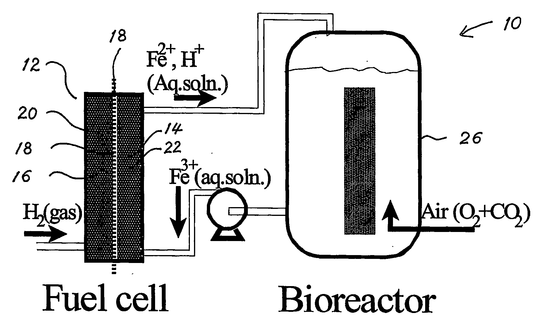
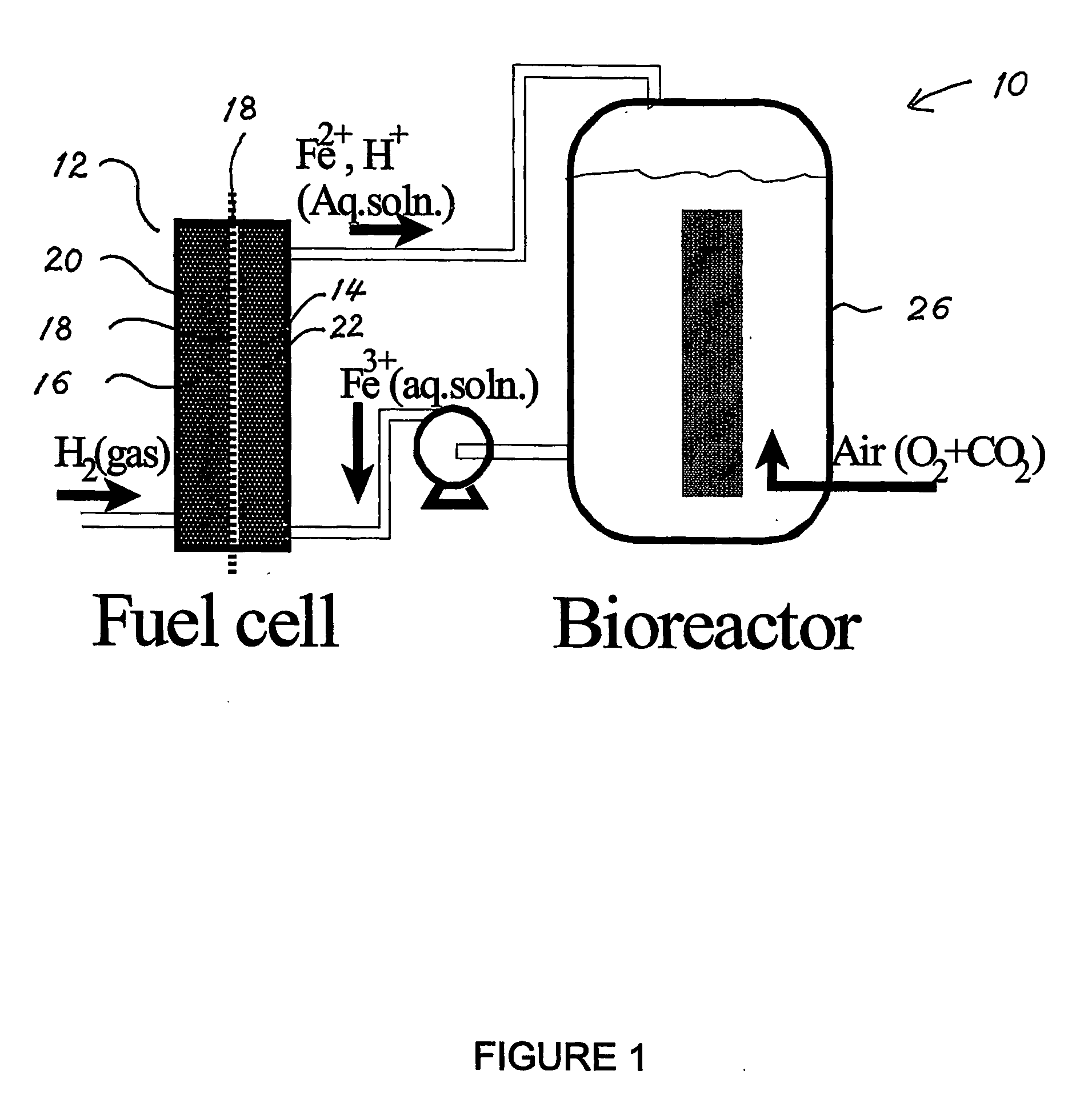
[0058] A preferred embodiment of a bio-fuel cell constructed in accordance with the present invention is based on the microbial oxidation of ferrous ions for the regeneration of the oxidant (ferric ions) in the fuel cell where the ferric iron are regenerated by Acidithiobacillus ferrooxidans (A. ferrooxidans) according to the reaction (1) above. Referring to FIG. 1, a bio-fuel cell-bioreactor system shown generally at 10 includes a fuel cell section 12 including a cathodic compartment 14 and an anodic compartment 16 separated by a membrane 18, such as for example a Nafion proton-exchange membrane. The anode 20 may be platinized carbon felt, while the cathode 22 may be a layer of carbon felt or some other inert material having a porous or otherwise high surface area. While the membrane is preferably a proton exchange membrane (PEM) other types of membranes may be used for separating physically the liquid in the cathode chamber from the gas (for example, hydrogen fuel) in the anodic s...


PUM

PropertyMeasurementUnit
diameteraaaaaaaaaa
solubilityaaaaaaaaaa

Abstract

The present invention discloses a new type of biofuel cell, based on the microbial regeneration of the oxidant, ferric ions. The bio-fuel cell is based on the cathodic reduction of ferric to ferrous ions, coupled with the microbial regeneration of ferric ions by the oxidation of ferrous ions, with fuel (such as hydrogen) oxidation on the anode. The microbial regeneration of ferric ions is achieved by chemolithotrophic microorganisms such as Acidithiobacillus ferroxidans. Electrical generation is coupled with the consumption of carbon dioxide from atmosphere and its transformation into microbial cells, which can be used as a single-cell protein.

Description

CROSS REFERENCE TO RELATED U.S. PATENT APPLICATION [0001] This application claims the benefit of priority from U.S. patent application Ser. No. 60 / 482,765 filed on Jun. 27, 2003, entitled BIOFUEL CELL, which application was filed in English.FIELD OF THE INVENTION [0002] The present invention relates to a fuel cell, and more particularly the present invention relates to a bio-fuel cell based on the microbial regeneration of the oxidant, ferric ions, by the process of aerobic oxidation of ferrous to ferric ions by chemolithotrophic microorganisms such as Acidithiobacillus ferroxidans that eliminates carbon dioxide from the atmosphere during electricity generation. BACKGROUND OF THE INVENTION [0003] A major component of the development of a hydrogen economy is the wide scale adoption of fuel cell technology. While there have been significant advances towards the application of fuel cells in everyday life, their widespread use has not been achieved yet due in part to the high cost of el...

Claims


Application Information

Patent Timeline
Patent Type & Authority Applications(United States)
IPC IPC(8): H01M8/16H01M8/10H01M8/20H01M8/06H01M8/18
CPCH01M4/8652Y02E60/528H01M4/9008H01M8/0293H01M8/04186H01M8/06H01M8/08H01M8/1067H01M8/16H01M8/18H01M8/188H01M8/20H01M2004/8689Y02E60/523Y02E60/527H01M4/90Y02E60/50
Inventor KARAMANEV, DIMITRE
Owner UNIV OF WESTERN ONTARIO
Learn More