Non-aqueous electrolyte secondary battery

Inactive Publication Date: 2006-11-09
PANASONIC CORP
View PDF11 Cites 15 Cited by
  • Summary
  • Abstract
  • Description
  • Claims
  • Application Information

AI Technical Summary

Benefits of technology

[0009] The present inventors made various studies and found that the porous heat-resistant layer described above, which excels in short-circuit resistance, has the effect of temporarily storing heat generated near an electrode. The present inventors also found that the porous heat-resistant layer has lower ion conductivity than the microporous resin separator. Presumably, this is because the resin (e.g., polyvinylidene fluoride, or PVDF), which is used as a binder during the formation of the porous heat-resistant layer together with an inorganic oxide filler, absorbs the electrolyte and thus swells, so that the ion conductivity becomes relatively

Problems solved by technology

However, when a high power lithium ion secondary battery is repeatedly discharged at high power, its capacity retention rate tends to be very low.
When seen microscopically, the separator melts and the micropores that contribute to ton conduction are gradually clogged, gradua

Method used


Image

  • Non-aqueous electrolyte secondary battery
  • Non-aqueous electrolyte secondary battery

Examples


Example

EXAMPLE 1

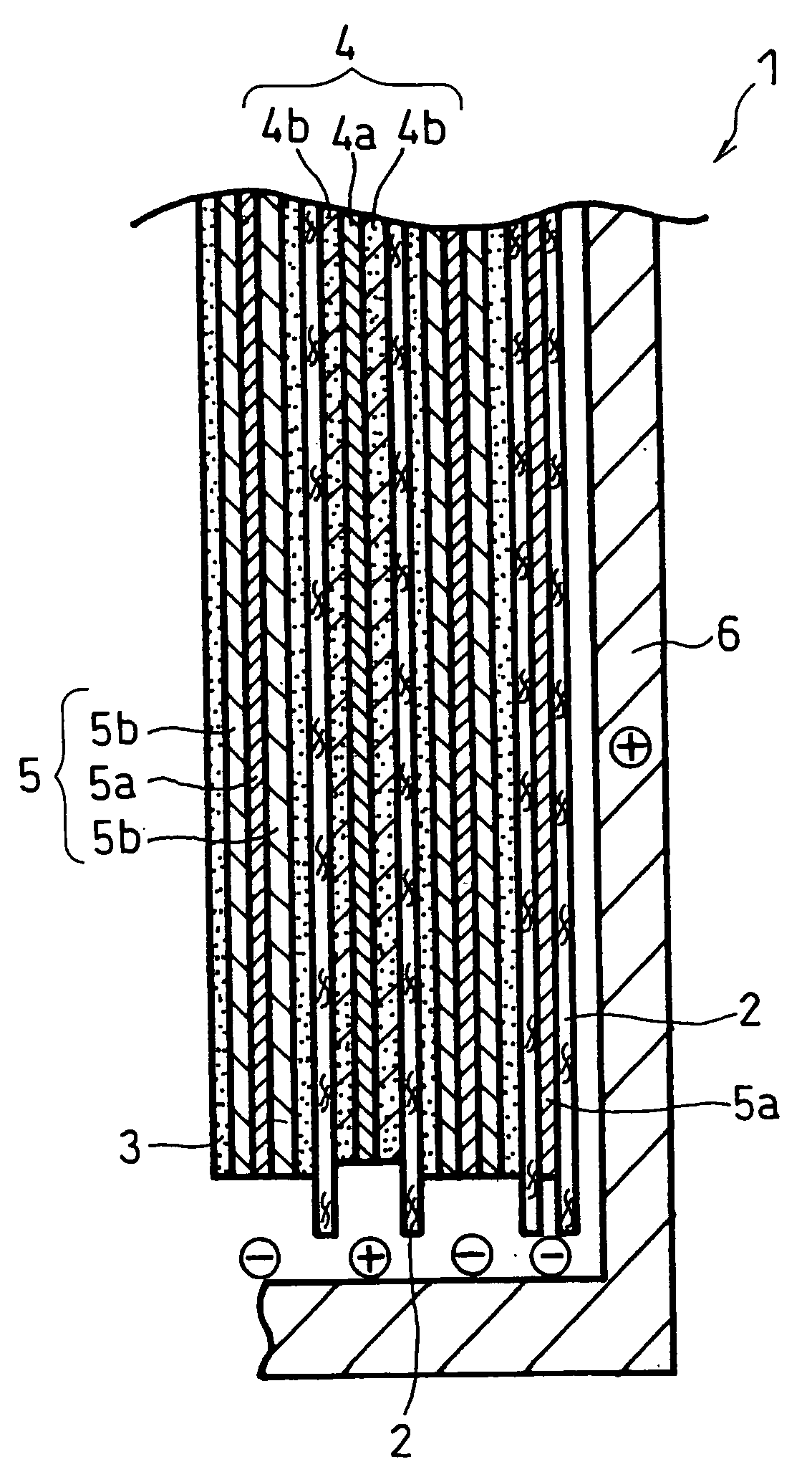
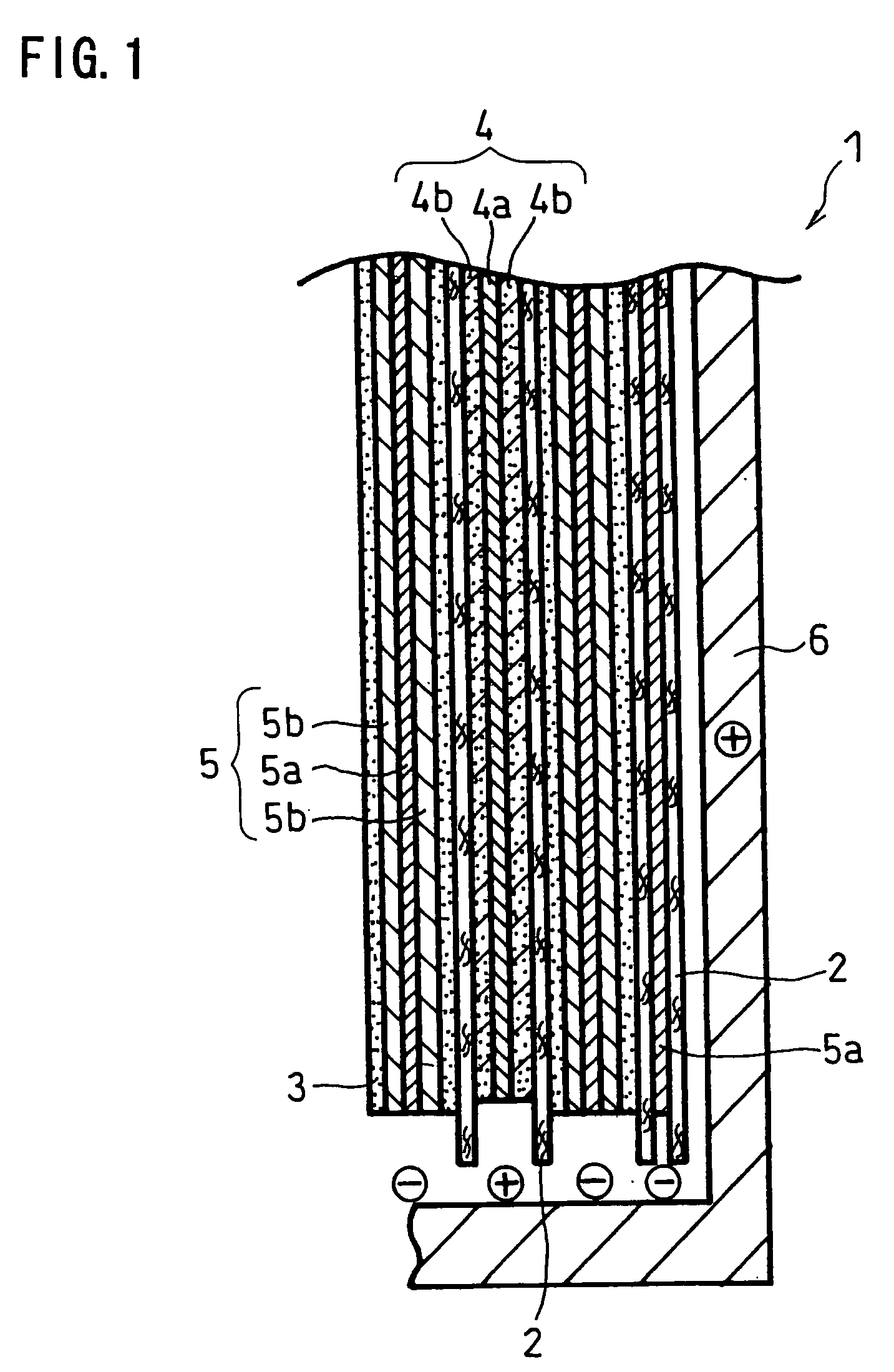
[0042] In this example, an electrode group having a structure shown in FIG. 1 was first produced.

[0043] A paste for forming positive electrode active material layer was prepared by mixing 30 kg of lithium cobaltate, 10 kg of PVDF #1320 (a N-methylpyrrolidone (NMP) solution with a solid content of 12 parts by weight), 900 g of acetylene black and an appropriate amount of NMP with a double arm kneader. The obtained paste for forming positive electrode active material layer was applied onto both surfaces of a 15 μm thick aluminum foil current collector, which was then dried and rolled to have a total thickness of 108 μm. Then, the resultant was cut into a size of 56 mm in width and 600 mm in length (each surface having an area of 336 cm2). Thereby, a positive electrode 4 was produced.

[0044] Meanwhile, a paste for forming negative electrode active material layer was prepared by mixing 20 kg of artificial graphite, 750 g of BM-400B (trade name) available from Zeon Corporation...

Example

EXAMPLES 2 TO 4

[0049] A cylindrical lithium ion secondary battery was produced in the same manner as in EXAMPLE 1 except that the thickness of the porous heat-resistant layer 3 was changed to 20 μm (EXAMPLE 2).

[0050] A cylindrical lithium ion secondary battery was produced in the same manner as in EXAMPLE 1 except that the thickness of the porous heat-resistant layer 3 was changed to 40 μm (EXAMPLE 3).

[0051] A cylindrical lithium ion secondary battery was produced in the same manner as in EXAMPLE 1 except that the thickness of the porous heat-resistant layer 3 was changed to 60 μm (EXAMPLE 4).

Example

EXAMPLE 5

[0052] A cylindrical lithium ion secondary battery was produced in the same manner as in EXAMPLE 2 except that the total thickness and the length of the positive electrode 4 were changed to 200 μm and 300 mm, respectively (area: 168 cm2), that the total thickness and the length of the negative electrode 5 were changed to 227 μm and 387 mm, respectively, and that a cylindrical battery case having a diameter of 17.5 mm was used. The produced battery had a positive electrode area per theoretical capacity of 198 cm2 / Ah.


PUM


Abstract

To provide a high power non-aqueous electrolyte secondary battery with high performance and less degradation in capacity even when high power discharge is repeated while maintaining the initial output characteristic by optimizing the insulating structure between the positive and negative electrodes, in a non-aqueous electrolyte secondary battery including a positive electrode, a negative electrode, a microporous resin separator and an electrolyte, an area per theoretical capacity of the positive electrode is set to 190 to 800 cm2/Ah and a porous heat-resistant layer having a thickness of 10 to 60 μm is provided between the separator and at least one of the positive electrode and the negative electrode.

Description

BACKGROUND OF THE INVENTION [0001] The present invention relates to a non-aqueous electrolyte secondary battery. More particularly, the invention relates to a high power non-aqueous electrolyte secondary battery. [0002] Non-aqueous electrolyte secondary batteries, particularly lithium ion secondary batteries, now have a high operating voltage and a high energy density. Accordingly, the application of lithium ion secondary batteries has been accelerated. They are used not only as power sources for driving portable electronic devices including cell phones, notebook computers and video camcorders, but also as power sources for devices that require high power such as power tools and electric vehicles. Particularly for hybrid electric vehicle (HEV) application, lithium ion secondary batteries are being actively developed as an alternative high capacity power source to replace nickel-metal hydride storage batteries that are currently available. High power lithium ion secondary batteries f...

Claims


Application Information

Patent Timeline
IPC IPC(8): H01M2/16H01M4/02H01M4/13H01M10/0525H01M10/0587H01M10/36
CPCH01M2/1673H01M4/02H01M4/13H01M6/42Y02T10/7011H01M10/0587H01M2004/021H01M2004/028Y02E60/122H01M10/0525H01M50/46Y02E60/10Y02P70/50H01M10/058H01M10/4235
Inventor NAKASHIMA, TAKUYANAGAYAMA, MASATOSHIMURAOKA, YOSHIYUKI
Owner PANASONIC CORP
Why Eureka
Try Eureka