
Electroconductive rubber roller

a technology of electroconductive rubber and roller, which is applied in the direction of manufacturing tools, portable power-driven tools, instruments, etc., can solve the problems of difficult to achieve stable volume resistivity, difficult to provide electroconductive rubber rollers of desired performance in a stable manner, uneven charging density of photosensitive components, etc., to achieve excellent permanent compression strain resistance, low hardness, and low electrical resistance

Active Publication Date: 2006-11-09
CANON KK
View PDF6 Cites 24 Cited by
  • Summary
  • Abstract
  • Description
  • Claims
  • Application Information

AI Technical Summary

Benefits of technology

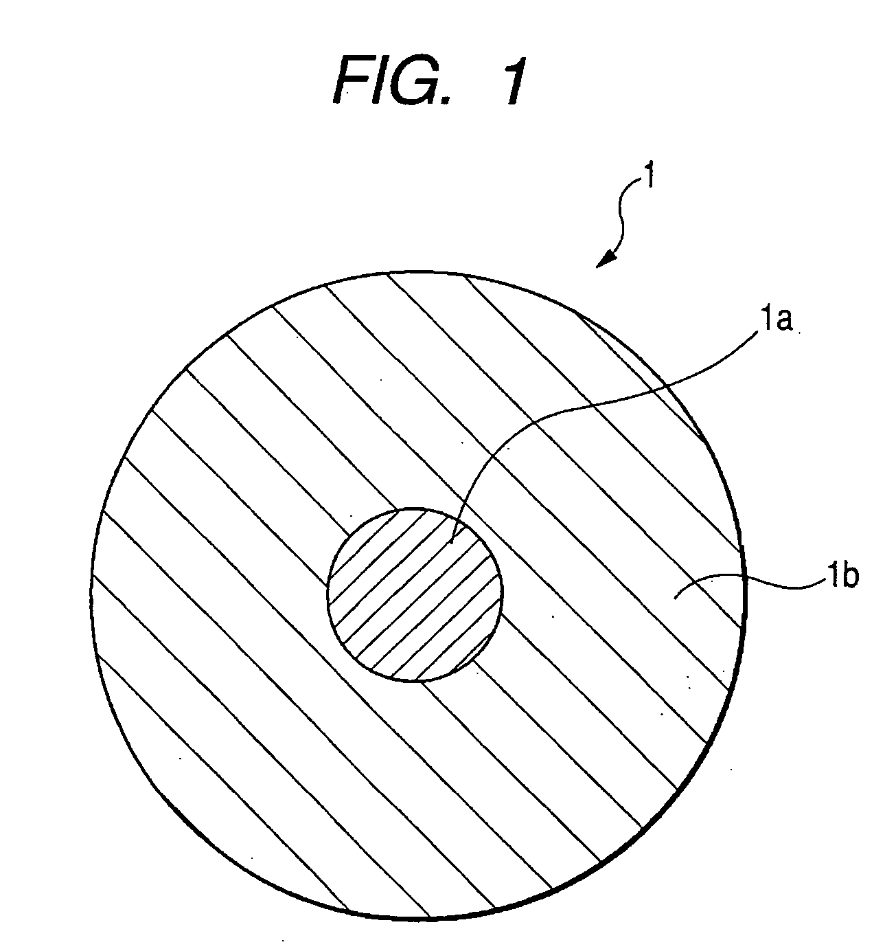
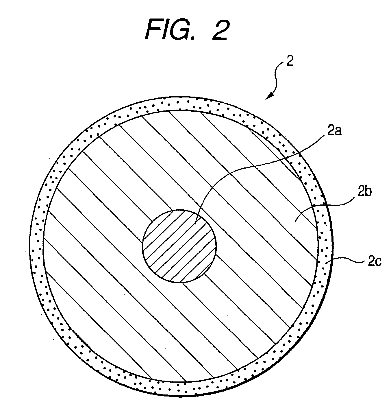
[0016] The present invention allows for obtaining an electroconductive rubber roller having a low electrical resistance and desirable electrical characteristics without deteriorating other characteristics such as electroconductivity or hardness, also having a low hardness and an excellent permanent compression strain resistance.

Problems solved by technology

Also in case the charging roller is electrically not uniform, the charging density on the photosensitive member becomes uneven reflecting such electrical non-uniformity.
Also the roller obtained in such method shows a significant dependence on the applied voltage, and a stable volume resistivity is difficult to attain.
However, an epichlorohydrin-based rubber with a high copolymerizing proportion of ethylene oxide, for example employed for preparing an electroconductive rubber roller of a low volume resistivity, is very difficult to provide electroconductive rubber rollers of desired performance in stable manner.
This is because in some cases such epichlorohydrin-based rubber, when employed in the preparation of rollers, results in a significant fluctuation in the performance of the rollers from lot to lot, also does not achieve a sufficient reduction in the volume resistivity of the rollers, also results in an unstable rubber hardness of the rollers after vulcanization and may lead to rollers of an abnormally low current value.
With a low current value, the roller is difficult to attain a required charging ability, and, when incorporated in an electrophotographic image forming apparatus, is unable to provide a satisfactory image.
Also with a high hardness, it is unable to secure a sufficient nip width when in contact with the photosensitive member and it may even cause a damage thereon.
These are fatal drawbacks in exhibiting the properties required for the electroconductive rubber roller.
However, the electroconductive rubber roller prepared with such material, though certainly showing an electroconductivity within the above-indicated range of the resistance value, shows a significant fluctuation in the electroconductivity from lot to lot of material, and is poorly practical as the electroconductive rubber roller for the image forming apparatus.
However, when the plasticizer is one ordinarily employed in the epichlorohydrin-based rubber, it may exude out from the electroconductive roller in a prolonged contact with the photosensitive member to cause a local deterioration thereof (stain on photosensitive member), thereby detrimentally affecting the reproduction images.
Therefore, the usable plasticizer has been limited in terms of the type and the blending amount thereof.

Method used


Image

  • Electroconductive rubber roller
  • Electroconductive rubber roller

Examples


examples

[0052] In the following, the present invention will be described further by examples thereof, but the present invention is not at all limited by such examples, in which “part” means part by mass.

[0053]

[0054] Epichlorohydrin-based rubbers of desired composition ratios were obtained by an ordinary solution polymerization, utilizing ethylene oxide, epichlorohydrin and allyl glycidyl ether in monomer compositions shown in Table 1. Also rubbers with different crystallinities were prepared by a temperature control of a heater provided in a polymerization reactor (autoclave), thereby controlling the proceeding of the polymerization reaction.

[0055]

[0056] Following components were kneaded in a closed kneader and open rolls to obtain an unvulcanized rubber composition:

Epichlorohydrin-based rubber (A to G) obtained100partsby the above-mentioned methodZinc oxide [trade name: Zinc Oxide Jis2,5partsmanufactured by Hakusui Tech Co.]Stearic acid [trade name: stearic acid S,1partmanufactured by ...


PUM

PropertyMeasurementUnit
enthalpyaaaaaaaaaa
enthalpyaaaaaaaaaa
volume resistivityaaaaaaaaaa

Abstract

An electroconductive rubber roller constituted of an electroconductive metal core and an electroconductive crosslinked rubber layer including an epichlorohydrin-based rubber, wherein the epichlorohydrin-based rubber is at least one copolymer selected from the group consisting of an epichlorohydrin-ethylene oxide copolymer and an epichlorohydrin-ethylene oxide-allyl glycidyl ether ternary copolymer. The ethylene oxide unit in the epichlorohydrin-based rubber is in a content of 40 to 90 mol %, and, the electroconductive crosslinked rubber layer has a heat quantity (enthalpy: ΔH) 5 mJ / mg or less as measured by a differential scanning calorimetry (DSC) and indicated by a peak appearing within a range of −20 to 150° C.

Description

BACKGROUND OF THE INVENTION [0001] 1. Field of the Invention [0002] The present invention relates to an electroconductive rubber roller such as a charging roller, a developing roller or a transfer roller, adapted for use in an image forming apparatus such as an electrophotographic apparatus or an electrostatic recording apparatus, as represented by a copying apparatus, a printer or a facsimile apparatus. [0003] 2. Related Background Art [0004] An image forming apparatus of electrophotographic process, such as a copying apparatus or a printer, has employed a process of depositing a toner on an electrostatic latent image and transferring such toner image onto a recording medium such as a transfer paper, thereby obtaining a print. More specifically, a photosensitive member is charged uniformly on its surface and is then exposed to an image projected by an optical system to dissipate the electrostatic charge in an exposed portion to form a latent image. Then, toner is deposited to form ...

Claims


Application Information

Patent Timeline
Patent Type & Authority Applications(United States)
IPC IPC(8): F16C13/00
CPCG03G15/0233G03G15/1685G03G15/0818C08L21/00
Inventor YAMADA, AKIHISAHASHIMOTO, MASAYUKIHARADA, NORIHIROHYUGA, MIHOKO
Owner CANON KK
Learn More