Anesthetic gas reclamation system and method

a technology of anesthetic gas and reclamation system, which is applied in the direction of lighting and heating apparatus, heating types, separation processes, etc., can solve the problem of creating significant quantities of waste anesthetic gas

Inactive Publication Date: 2006-11-16
ANESTHETIC GAS RECHAMATION LLC
View PDF95 Cites 15 Cited by
  • Summary
  • Abstract
  • Description
  • Claims
  • Application Information

AI Technical Summary

Benefits of technology

[0008] A primary object of the invention is to provide an economical system and method for removing fluoro-ethers and other volatile halocarbons from waste anesthetic gases from a surgical facility before such gases are vented to the atmosphere.

Problems solved by technology

The administration of anesthesia in surgical and other healthcare facilities creates significant quantities of waste anesthetic gases.
Although it is anticipated that regulation of these emissions will occur in the near future, currently no such regulation exists.

Method used


Image

  • Anesthetic gas reclamation system and method
  • Anesthetic gas reclamation system and method
  • Anesthetic gas reclamation system and method

Examples


third embodiment

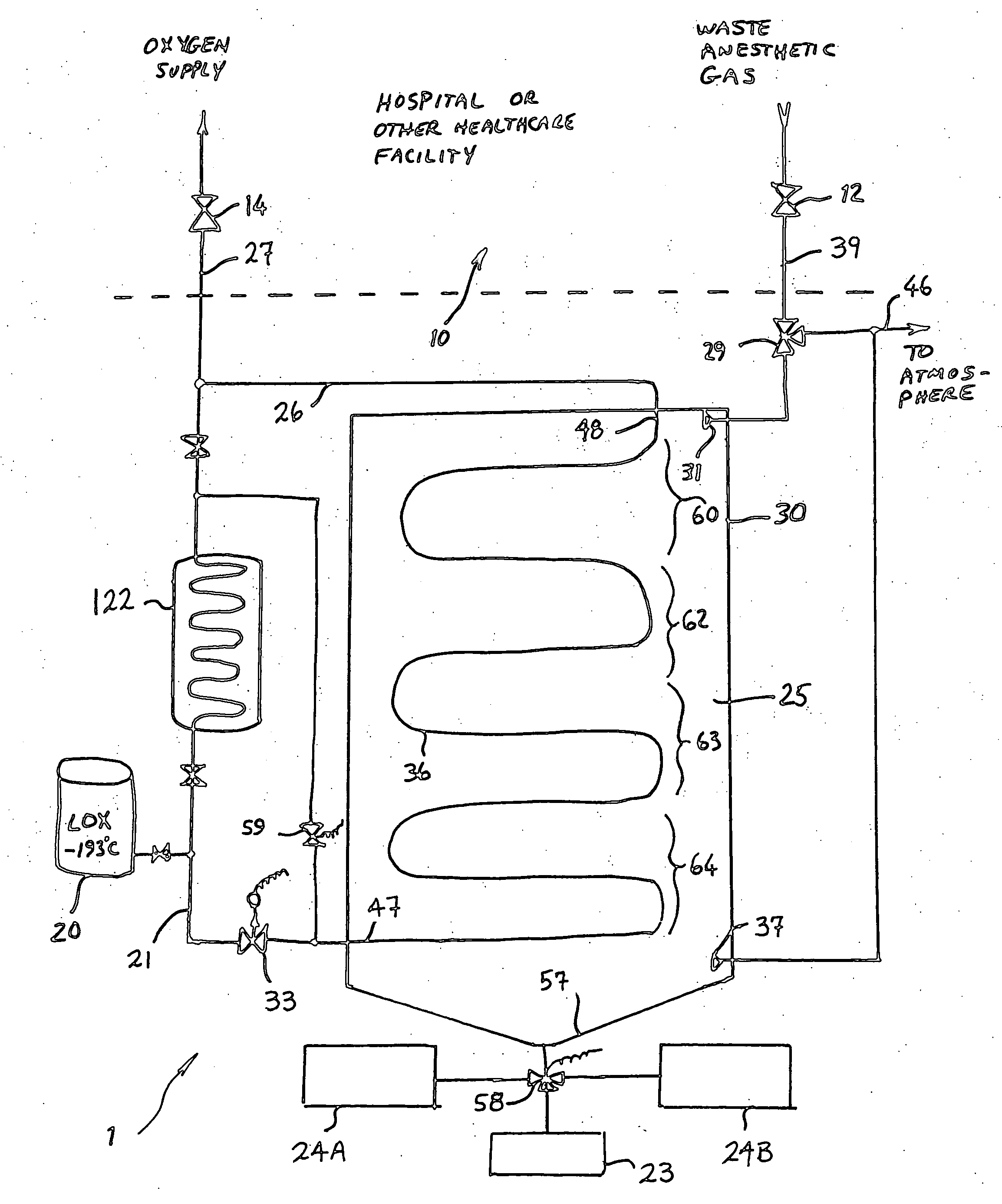
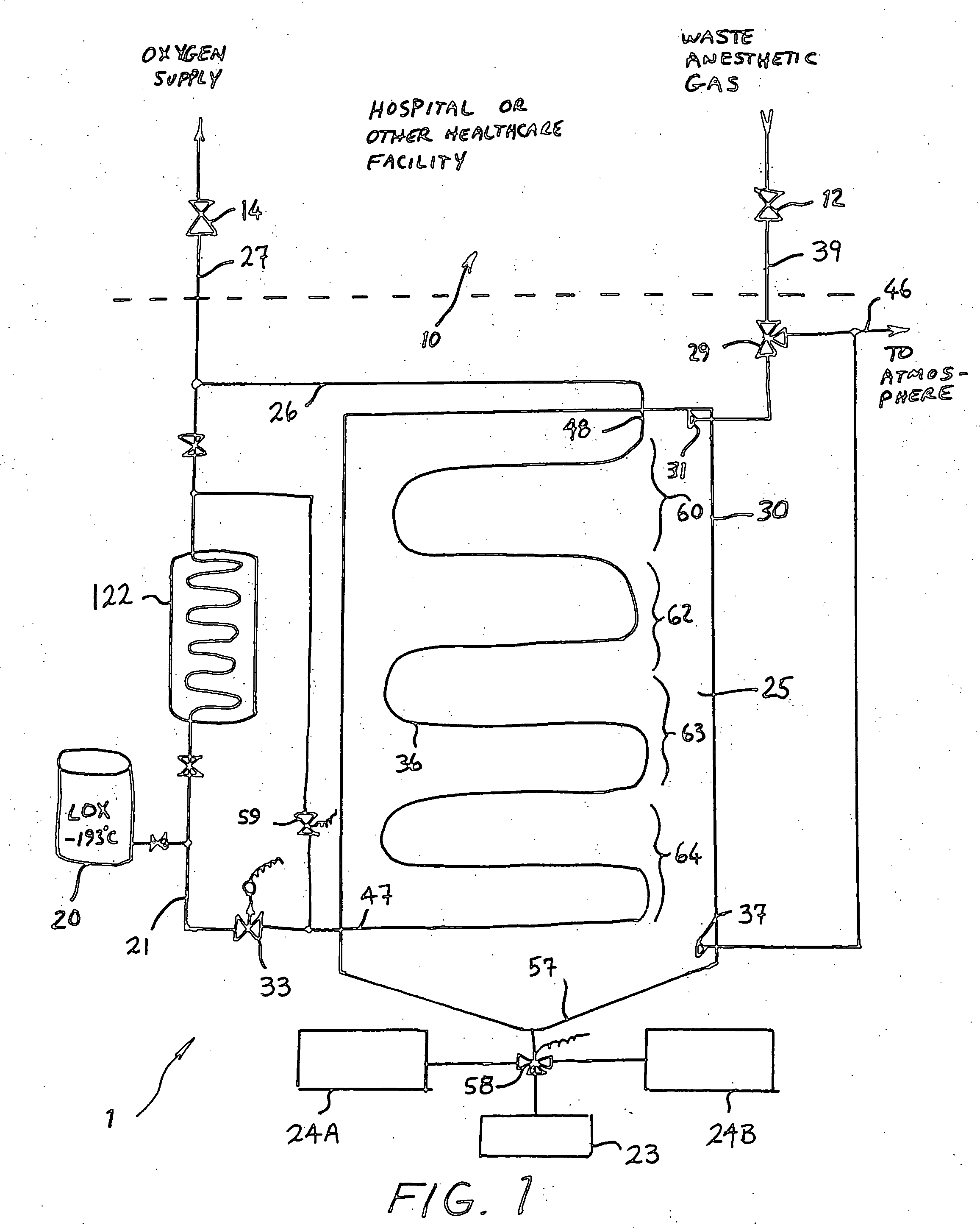
[0028] The cold trap / fractionator 25 is periodically cycled through a thaw process. During the thaw cycle, the cold trap / fractionator 25 is slowly warmed to about 0° C. to defrost the cooling coils 36. Warming is achieved by reducing or securing the flow of liquid oxygen through cooling coils 36 by thermostatic control valve 33 and allowing the cold trap / fractionator 25 to warm to room temperature by heat transfer with its surroundings. In an alternate embodiment, warm oxygen from heat exchanger 122 may be directed through the cooling coils 36 by opening valve 59 to increase the thaw rate. In yet a third embodiment, another fluid (not shown) may be directed through cooling coils 36 to achieve a controlled thaw.

[0029] The bottom end 57 of enclosure 30 is funnel-shaped and acts as a hopper. The lowest point preferably drains into a 4-way selector valve 58, which in turn is fluidly coupled to three drain tanks 23, 24A, 24B. At sufficiently high pressures (i.e., typically atmospheric pr...

embodiment 1

[0038] As shown in FIG. 3, reclamation system 3 includes additional equipment, such as a gaseous anesthetic collection tank 24C, a 3-way collection valve 56, an optional vacuum pump 92 and an optional source of nitrogen or other gas 89 with an accompanying isolation valve 90. Collection valve 56, 3-way selector valve 29, and nitrogen isolation valve 90 (if present) are all preferably controlled by the control system (not shown) previously described for use with embodiment 1 of FIG. 1. During the trap mode of operation, collection valve 56 is positioned so that outlet fitting 37 is fluidly coupled to the atmospheric discharge vent 46. Waste anesthetic gas enters the cold trap / fractionator 25 through inlet 31, passes over cooling coils 36 to trap water vapor, nitrous oxide, fluoro-ethers, and other volatile halocarbons, and then passes to the atmosphere through outlet 37, nitrous oxide collection valve 56, and vent line 46. Because fluoro-ethers and other halocarbon anesthetics are ge...


PUM

PropertyMeasurementUnit
temperatureaaaaaaaaaa
pressuresaaaaaaaaaa

Abstract

A method and system for the fractionation and removal of nitrous oxide and other volatile halocarbon gas components from waste anesthetic gases using liquid oxygen are disclosed. Liquid oxygen is warmed for use in a healthcare facility by cooling and condensing waste anesthetic gases. A cold trap/fractionator is provided wherein selective components of the waste anesthetic gas are collected as a frost on the coils of the cold trap/fractionator by desublimation/deposition and/or condensation/solidification. In a periodic batch process, the collected frost is first thawed and the melted liquids or gases are then collected at various increasing temperatures, thereby separating the nitrous oxide and other halocarbon gas components by their varying melting points. The thawed anesthetic components are collected in separate tanks based on their melting points. Warmed by the waste anesthetic gases in the cold trap/fractionator, the oxygen is supplied to the healthcare facility for its normal uses.

Description

CROSS REFERENCE TO RELATED APPLICATION [0001] This application is based upon provisional applications 60 / 680,644 filed on May 13, 2005 and 60 / 682,249 filed on May 18, 2005, the priorities of which are claimed.BACKGROUND OF THE INVENTION [0002] 1. Field of the Invention [0003] This invention concerns treatment of waste anesthetic gas. In particular the invention pertains to the removal and reclamation of nitrous oxide, fluoro-ethers, and other halocarbons from waste anesthetic gas of a healthcare facility before the gas is discharged to the atmosphere in order to decrease atmospheric pollution. [0004] 2. Description of the Prior Art [0005] The administration of anesthesia in surgical and other healthcare facilities creates significant quantities of waste anesthetic gases. Currently these gases are scavenged, diluted with air in a system of dedicated pipes, and then vented to the atmosphere outside the building. The average composition of the waste gases is estimated to be (in percent...

Claims


Application Information

Patent Timeline
Patent Type & Authority Applications(United States)
IPC IPC(8): A61M16/00
CPCY02C20/10A61M16/009A61M2202/0208A61M2202/03A61M2202/0007
Inventor BERRY, JAMES M.MORRIS, STEVE
Owner ANESTHETIC GAS RECHAMATION LLC
Why Eureka
Try Eureka