
Frequency agile, directive beam patch antennas

a beam patch and antenna technology, applied in the direction of individual energised antenna arrays, resonant antennas, radiating element structural forms, etc., can solve the problem of poor power handling capability of mems varactors and low loss

Inactive Publication Date: 2006-11-16
PARATEK MICROWAVE INC
View PDF7 Cites 19 Cited by
  • Summary
  • Abstract
  • Description
  • Claims
  • Application Information

AI Technical Summary

Benefits of technology

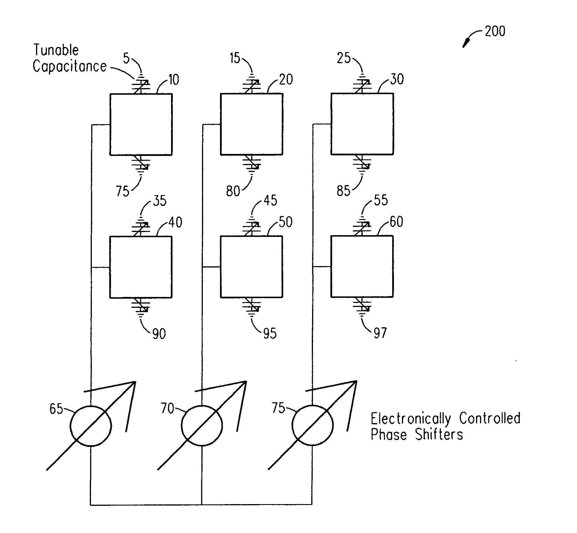
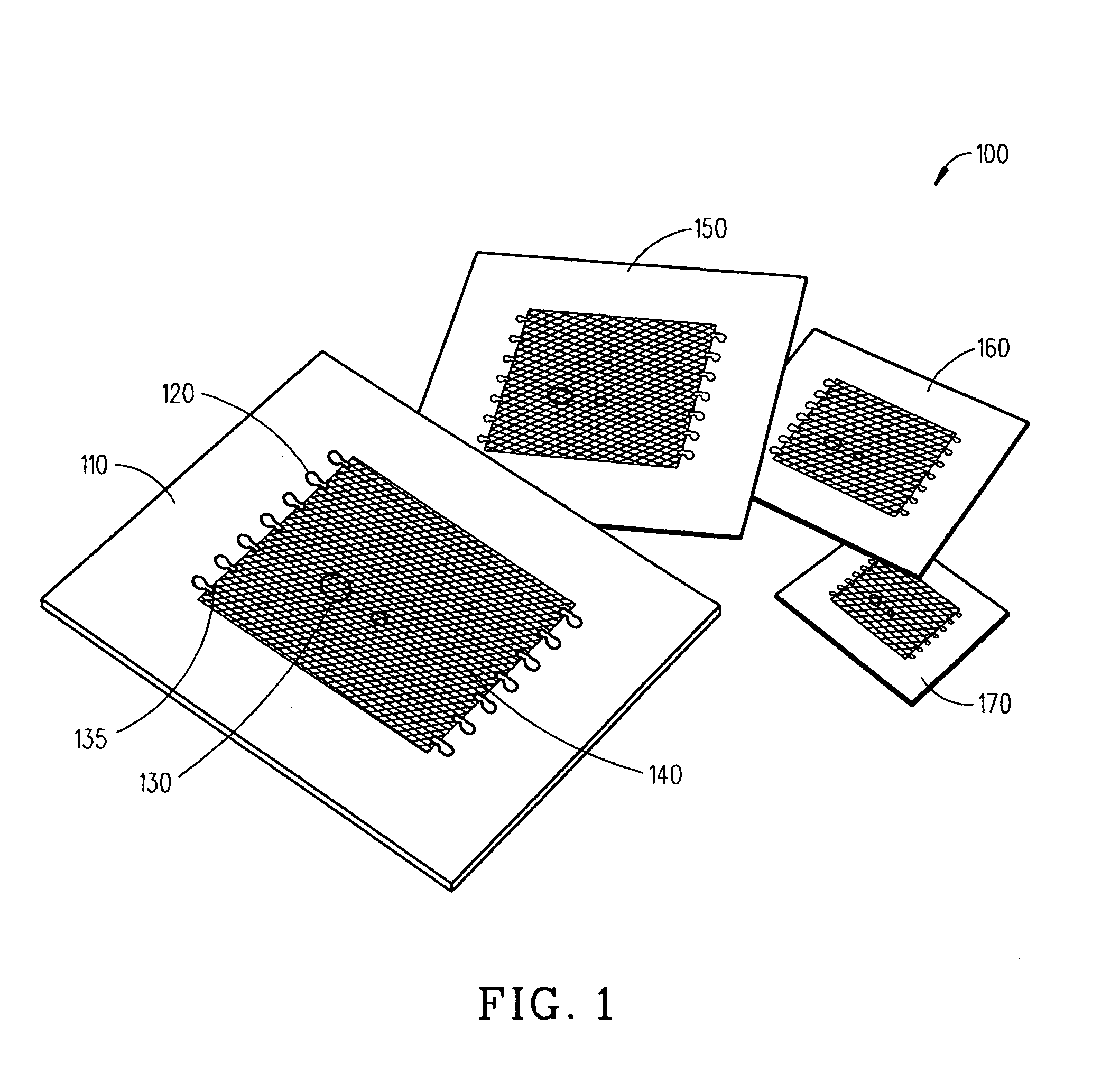
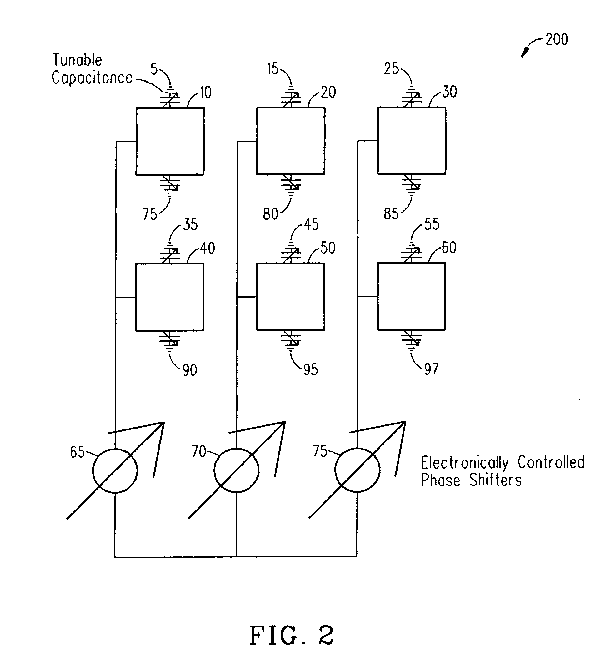
[0004] The present invention provides a beam steering, frequency agile antenna having low insertion loss, fast tuning speed, high power-handling capability, high IP3 and low cost in the microwave frequency range. More specifically, this is provided for by a frequency agile, directive beam patch antenna, comprising an array of antenna elements, said antenna array elements loaded with tunable dieletric capacitors in order to tune their frequency response; and an electronic phase shifter controlling said array of antenna elements in order to spatially scan the main radiation beam, said tunable dielectric capacitor comprising a substrate having a low dielectric constant with planar surfaces, a tunable dielectric film on said substrate of low loss tunable dielectric material, metallic electrodes with predetermined length, width, and gap distance; and low loss isolation material used to isolate an outer bias metallic contact and a metallic electrode on said tunable dielectric.

Problems solved by technology

MEMS varactors have low loss but very poor power handling capability.

Method used


Image

  • Frequency agile, directive beam patch antennas
  • Frequency agile, directive beam patch antennas
  • Frequency agile, directive beam patch antennas

Examples


Embodiment Construction

[0010] Inherent in every tunable element is the ability to rapidly tune the response using high-impedance control lines. Paratek, the assignee of the present invention, has developed a tunable material technology, trademarked as Parascan® materials, that enables these tuning properties, as well as, high Q values, low losses and extremely high IP3 characteristics, even at high frequencies. MEM based varactors can also be used for this purpose. They use different bias voltages to vary the electrostatic force between two parallel plates of the varactor and hence change its capacitance value. They show lower Q than dielectric varactors, and have worse power handling, but can be used successfully for some applications. Also, diode varactors could be used to make tunable elements, although with worse performance than dielectric varactors. Tunable dielectric materials are the materials whose permittivity (more commonly called dielectric constant) can be varied by varying the strength of an...


PUM


Abstract

An embodiment of the present invention provides an apparatus, comprising a frequency agile, directive patch antenna in a phased array with frequency agile elements, wherein the directive patch antenna is capable of generating a main radiation beam that is capable of being steered using electronically controlled phased shifters and wherein at least one tunable capacitors controls the resonant response of individual antenna elements within the phased array.

Description

CROSS-REFERENCE TO RELATED APPLICATION [0001] This application is a continuation application of U.S. patent application Ser. No. 10 / 413,107, entitled, “FREQUENCY AGILE, DIRECTIVE BEAM PATCH ANTENNAS”, filed Apr. 14, 2003, which claimed the benefit of priority under 35 U.S.C Section 119 from U.S. Provisional Application Ser. No. 60 / 372,741, filed Apr. 15, 2002, entitled, FREQUENCY AGILE, DIRECTIVE BEAM PATCH ANTENNAS, by Sengupta et al., assigned to Paratek Microwave, Inc. BACKGROUND OF THE INVENTION [0002] The present invention generally relates to tunable antennas, phased array antennas, tunable dielectric capacitors, and semiconductor varactors and more specifically to the aforementioned in frequency agile, directive beam patch antennas. [0003] Scanning, phased array antennas have numerous applications in both the commercial and military markets. The antenna is comprised of smaller antenna elements arranged in a specific pattern and a given differential phase shift in order to ste...

Claims


Application Information

Patent Timeline
Patent Type & Authority Applications(United States)
IPC IPC(8): H01Q1/38H01Q9/00H01Q3/26H01Q9/04H01Q21/06
CPCH01Q1/38H01Q21/065H01Q9/0442H01Q3/26
Inventor SENGUPTA, LOUISE C.EKELMAN, ERNESTBROWN, WILLIAM
Owner PARATEK MICROWAVE INC
Learn More