Tubular metal body, method of producing same, liner for pressure vessel and method of producing same

Inactive Publication Date: 2006-11-23
SHOWA DENKO KK +1
View PDF8 Cites 22 Cited by
  • Summary
  • Abstract
  • Description
  • Claims
  • Application Information

AI Technical Summary

Benefits of technology

[0046] The third pressure vessel liner described can be produced

Problems solved by technology

Furthermore, the tubular body can b

Method used


Image

  • Tubular metal body, method of producing same, liner for pressure vessel and method of producing same
  • Tubular metal body, method of producing same, liner for pressure vessel and method of producing same
  • Tubular metal body, method of producing same, liner for pressure vessel and method of producing same

Examples


embodiment 1

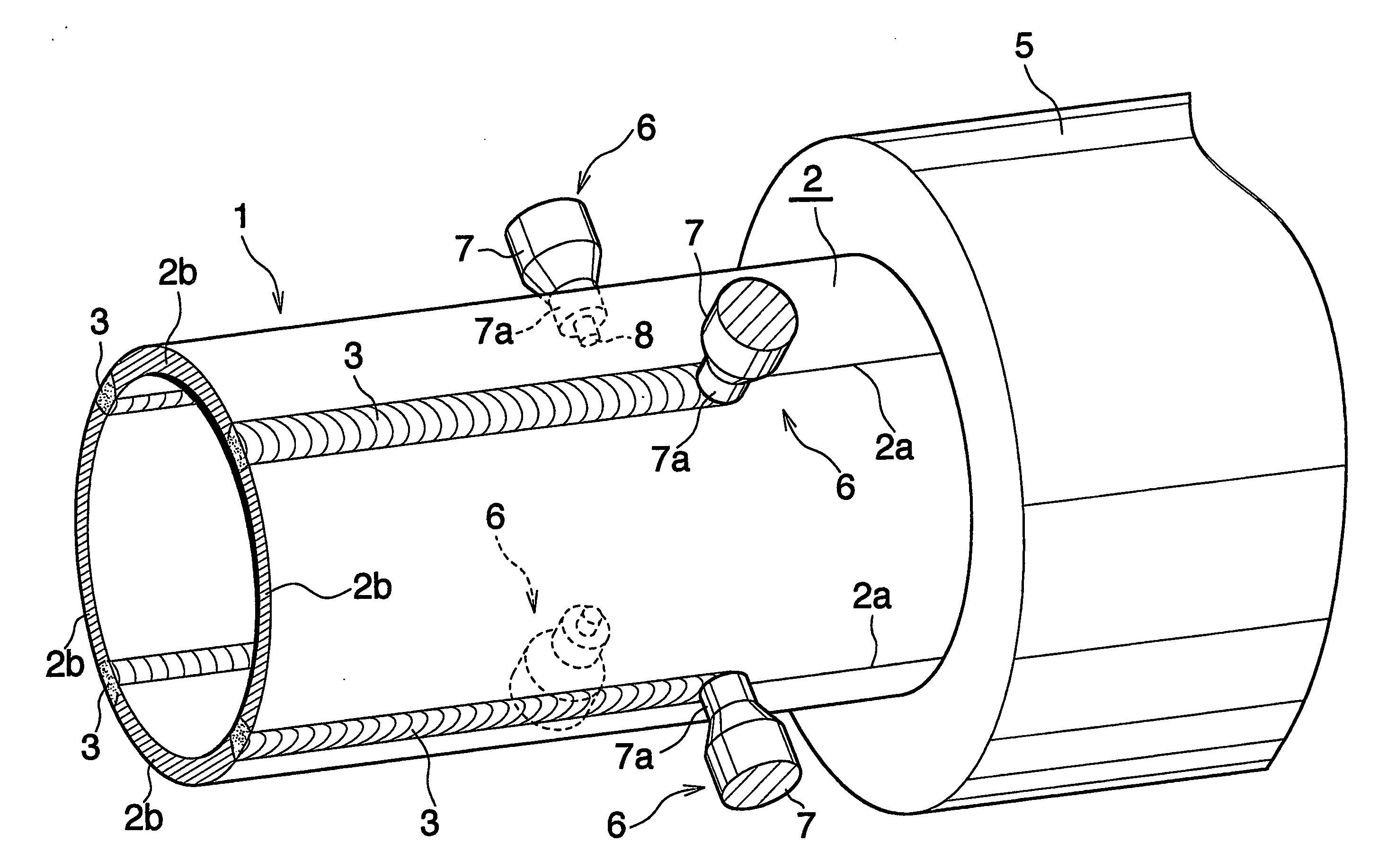
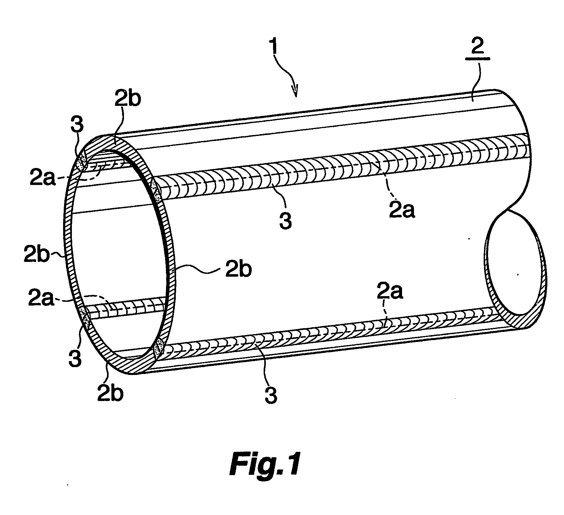
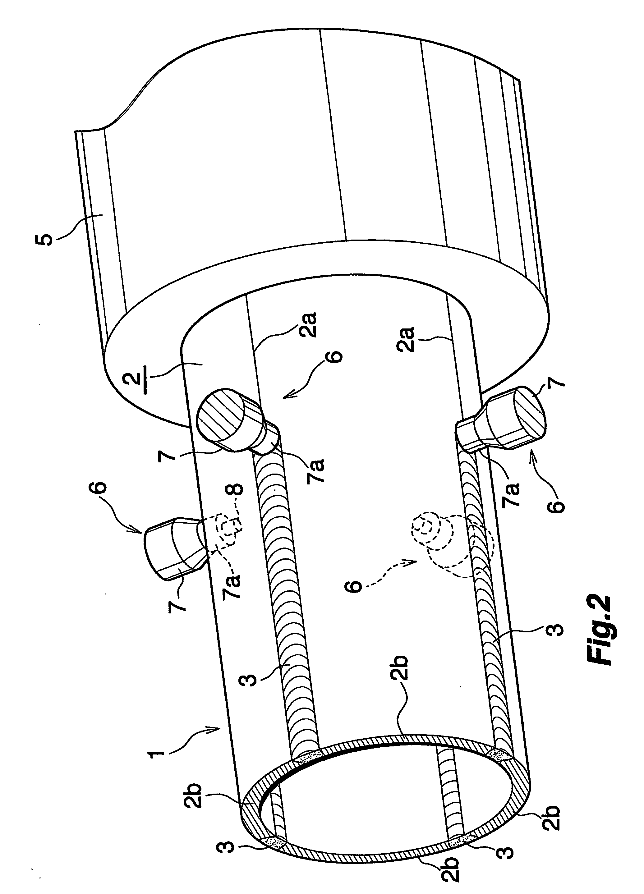
[0067] This embodiment is shown in FIGS. 1 to 3.

[0068]FIG. 1 shows a tubular metal body according to Embodiment 1, and FIGS. 2 and 3 show a method of producing the same.

[0069] With reference FIG. 1, the tubular metal body 1 comprises a porthole die-extruded tube 2 having a circular cross section and comprising a plurality of, more specifically four, components 2b which are joined to one another with a plurality of, i.e., four, joint portions 2a extending over the entire length of the tube. The metal serving as the base material of the extruded tube 2 is subjected to a modifying treatment at each of the joint portions 2a to produce finely divided crystal grains in a striplike portion having a specified width and including the joint portion 2a. The modified portion is indicated at 3.

[0070] The die-extruded tube 2 is made, for example, from one of JIS A2000 alloy, JIS A5000 alloy, JIS A6000 alloy and JIS A7000 alloy.

[0071] The base material is modified by friction agitation using a...

embodiment 2

[0079] This embodiment is shown in FIGS. 4 to 6.

[0080]FIG. 4 shows a tubular metal body according to Embodiment 2, and FIGS. 5 and 6 show a method of producing the tubular metal body.

[0081] With reference to FIG. 4, the tubular metal body 10 comprises a porthole die-extruded tube 2 which is fixedly provided inside thereof with a reinforcing partition 11 extending over the entire length thereof and dividing the interior of the body 10 into a plurality of spaces. The tube 2 and the partition 11 have the same length and have their corresponding ends at the same position. The reinforcing partition 11 comprises four integral partition walls 11a extending radially from the center line of the tube 2 and equal in number to the number of joint portions 2a, and is in the form of a cross in cross section. Each of the partition walls 11a has an outer end joined by friction agitation to the tube 2 at the joint portion 2a. The reinforcing partition 11 is made, for example, from one of JIS A2000...

embodiment 3

[0091]FIG. 7 shows this embodiment.

[0092] With reference to FIG. 7, the embodiment, i.e., a tubular metal body 15, comprises a porthole die-extruded tube 2 which is elliptical in cross section. The metal body 15 has the same structure as the metal body 10 of Embodiment 2 with the exception of the above feature and is produced by the same method as the metal body 10 of Embodiment 2.


PUM

PropertyMeasurementUnit
Lengthaaaaaaaaaa
Electrical resistanceaaaaaaaaaa
Sizeaaaaaaaaaa

Abstract

A tubular metal body 1 comprises a tube 2 extruded through a porthole die and composed of a plurality of components 2b joined to one another with a plurality of joint portions 2a extending over the entire length of the tube. The base material metal of the extruded tube 2 in each of the joint portions 2a is subjected to a modifying treatment to produce finely divided crystal grains. The modifying treatment for the extruded tube 2 is conducted preferably by frictionally agitating each joint portion using a probe 8 of a friction agitation joining tool 6. The tubular metal body 1 is available with an increased length in a larger size and has high pressure resistance.

Description

CROSS REFERENCE TO RELATED APPLICATIONS [0001] This application is an application filed under 35 U.S.C. §111(a) claiming the benefit pursuant to 35 U.S.C. §119(e) (1) of the filing date of Provisional Applications No. 60 / 469,002 and No. 60 / 469,023 each filed May 9, 2003 pursuant to 35 U.S.C. §111(b).TECHNICAL FIELD [0002] The present invention relates to tubular metal bodies for use in high-pressure piping, for example, for motor vehicles, houses, transport machines, etc. for passing therethrough fuel hydrogen gas or natural gas of high pressure serving as a fuel for power generation and to a method of producing the same. [0003] The present invention relates also to liners for use in pressure vessels for storing hydrogen gas or natural gas serving as a fuel for power generation, for example, in motor vehicles, houses, transport machines, etc. or for use in pressure vessels for storing oxygen gas in oxygen gas supply systems and to a method of producing the liner. BACKGROUND ART [000...

Claims


Application Information

Patent Timeline
IPC IPC(8): B21C25/04B21C23/08B23K20/12F17C1/14H01M8/04
CPCB21C23/085B21C35/02B21C35/023B21C37/08B21C37/0803B21C37/151B23K20/122B23K20/1265B23K20/1275B23K2201/12F17C1/14F17C2201/0109F17C2201/0119F17C2201/0128F17C2201/0147F17C2201/0166F17C2201/054F17C2201/056F17C2203/012F17C2203/0604F17C2203/0617F17C2203/0619F17C2203/0636F17C2203/0646F17C2203/0648F17C2203/0663F17C2209/222F17C2209/23F17C2209/232F17C2221/011F17C2221/012F17C2221/033F17C2223/0123F17C2223/035F17C2260/011F17C2260/053F17C2270/0168F17C2270/0184F17C2270/07F17C2270/0763H01M8/04089Y02E60/321B21C23/14B23K2101/12Y02E60/32Y02E60/50B21C23/00B23K20/12
Inventor OSAME, YOSUHIRO
Owner SHOWA DENKO KK
Why Eureka
Try Eureka