DC to DC converter and voltage detecting circuit and current detecting circuit thereof

a technology of voltage detection circuit and detecting circuit, which is applied in the direction of pulse circuit, pulse manipulation, multiple input and output pulse circuit, etc., can solve problems such as unpractical devices, and achieve the effect of eliminating the influence of input offset voltage in the operational amplifier easily and securely

Inactive Publication Date: 2006-11-23
FUJI ELECTRIC CO LTD
View PDF7 Cites 28 Cited by
  • Summary
  • Abstract
  • Description
  • Claims
  • Application Information

AI Technical Summary

Benefits of technology

[0014] After the capacitor is charged once with the voltage corresponding to the DC or AC voltage, the voltage can be compared with the voltage corresponding to the AC or DC voltage. Thus, the influence of the input offset voltage in the operational amplifier can be eliminated easily and securely.

Problems solved by technology

Therefore, when comparing the two voltages by an ordinary amplifier, a large error can occur because of the variation in the input offset voltage, thus making such a device unpractical.

Method used


Image

  • DC to DC converter and voltage detecting circuit and current detecting circuit thereof
  • DC to DC converter and voltage detecting circuit and current detecting circuit thereof
  • DC to DC converter and voltage detecting circuit and current detecting circuit thereof

Examples


first embodiment

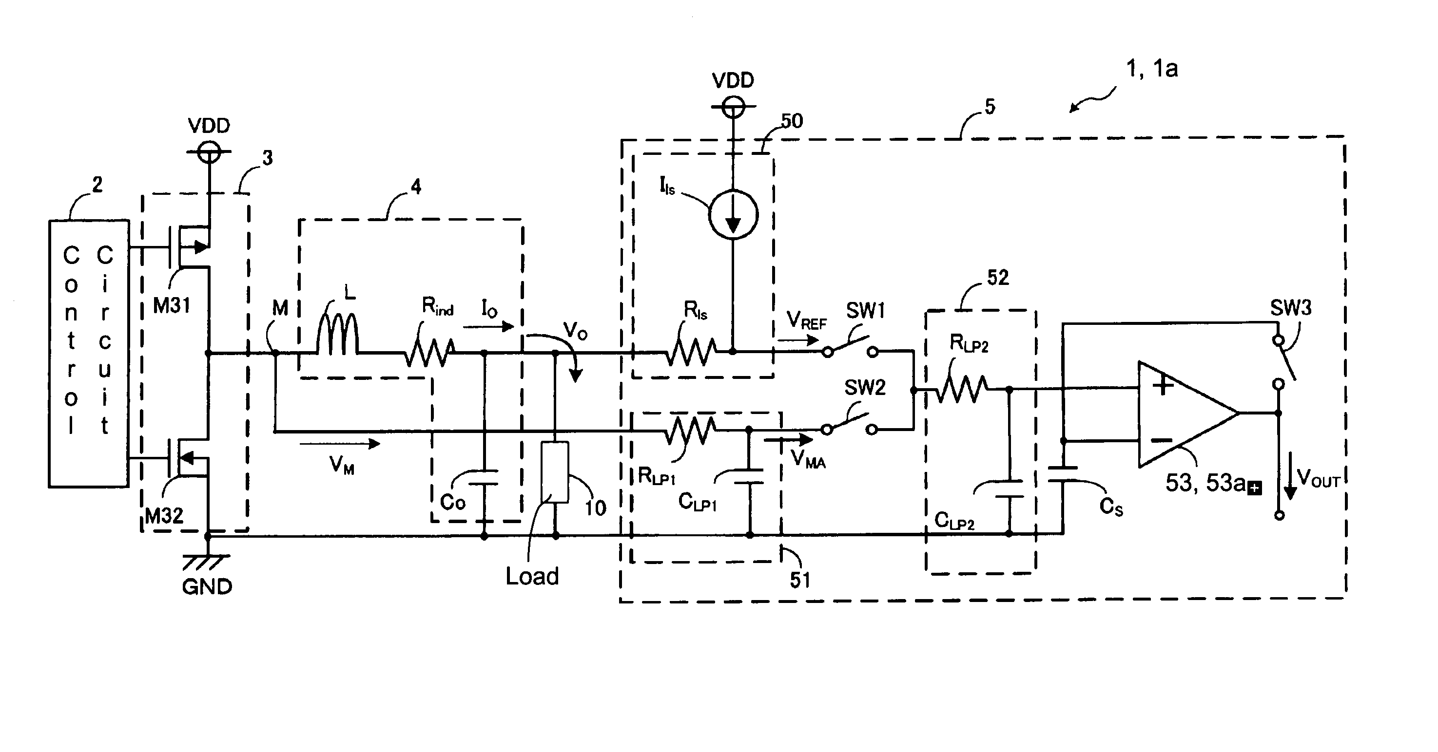
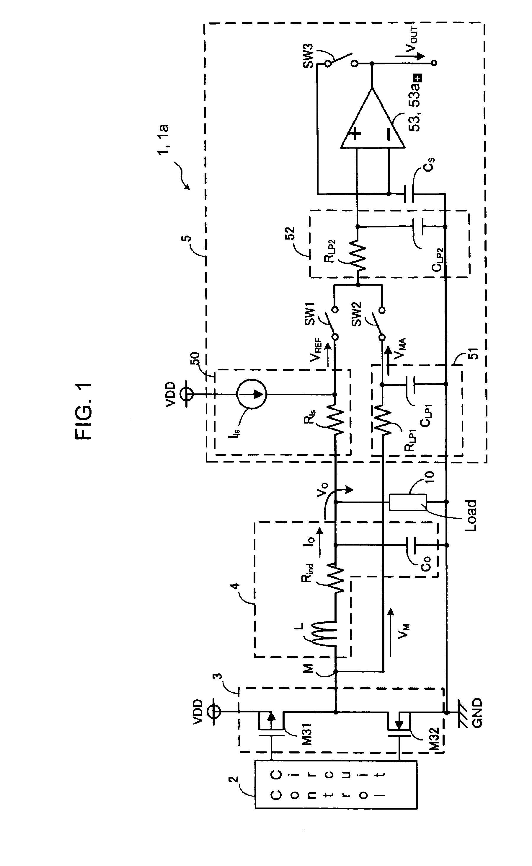
[0032] As described above, in the DC to DC converter 1, instead of directly comparing the voltages VREF and VMA applied to the current detecting circuit 5, the capacitor CS is charged once with the voltage VREF and then the voltage VREF is compared with the voltage VMA. That is, the detecting method in the current detecting circuit 5 can be expressed by the following equation (5):

(VMA−ΔVIN)−(VREF−ΔVIN)=VMA−VREF   (5).

[0033] Since the voltage held in the capacitor CS changes in accordance with the magnitude of the input offset voltage ΔVIN of the operational amplifier 53, the magnitude of the input offset voltage ΔVIN does not influence the result of the comparison. That is, the influence of the offset voltage ΔVIN of the operational amplifier 53 can be eliminated easily and securely. Thus, more accurate voltage detection can be carried out than in the case of inputting the voltages VREF and VMA to the comparator and comparing these voltages. That is, even if the offset voltage ΔVIN...

second embodiment

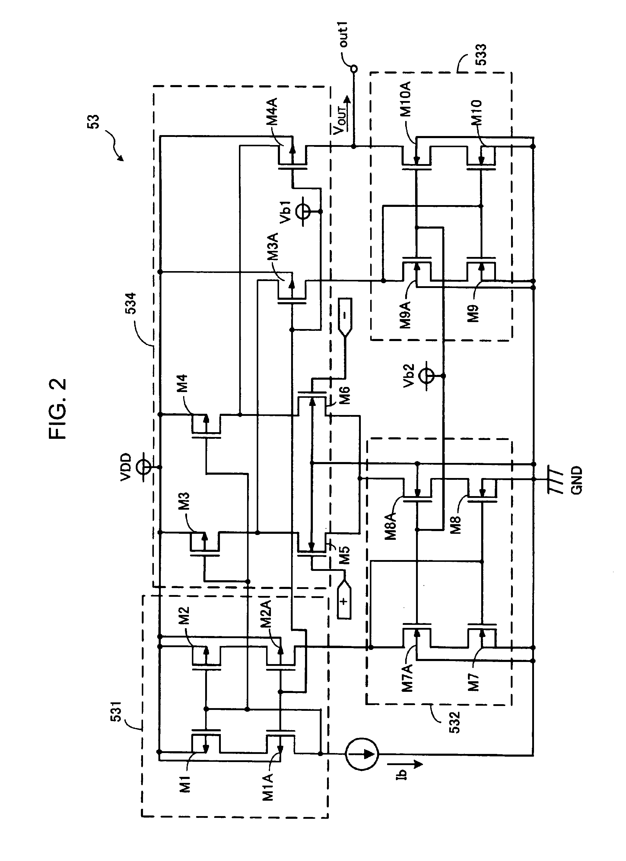
[0039] Referring to FIG. 3, which illustrates a circuit diagram of an operational amplifier 53a in the DC to DC converter 1a (second embodiment), the operational amplifier 53a has a two-stage amplification. The operational amplifier 53a has a constant-current circuit 531a, which includes NMOS transistors M15, M16, and M18, a differential amplification stage 532a, which includes PMOS transistors M13 and M14 and NMOS transistors M11 and M12, a PMOS transistor M17 forming the second amplification stage, and a phase compensation circuit 533a arranged between the gate and drain of the transistor Ml 7.

[0040] The phase compensation circuit 533a is arranged for providing phase compensation by Miller effect and has a switch SW11, a resistor RC and a capacitor CC connected in series in this order from the gate side to the drain side of the transistor M17, and a switch SW12 arranged between the drain-side terminal of the switch SW11 and the drain of the transistor M17. Each of the switches SW1...


PUM


Abstract

A DC to DC converter includes a current detecting circuit having a level shift circuit, which includes a resistor and a current source. A first low-pass filter is led out from a node via a signal line and includes a resistor and a capacitor. A first switch is provided after the level shift circuit, a second switch is provided after the low-pass filter, a second low-pass filter, which includes a resistor and a capacitor, an operational amplifier, a third switch is provided between an output terminal and an inverted input terminal of the operational amplifier, and a capacitor is provided between the inverted input terminal of the operational amplifier and GND. An output current is detected with high accuracy without lowering the efficiency by detection resistance.

Description

BACKGROUND [0001] A conventional DC to DC converter circuit, such as a step-down synchronous rectification switching converter, acquires a DC voltage, different from a DC power having a substantially constant voltage, by switching a transistor element. In such a DC to DC converter circuit, for example, when providing overcurrent protection for a load or detecting a light load state having a small output current and realizing a function of automatically shifting to a light load mode, an average current actually supplied to the load must be detected, as disclosed in JP-A-2005-65447 and US 2005 / 0057229 A1. [0002]FIG. 4 is a circuit diagram showing a current detecting device 90 of a conventional DC to DC converter. The current detecting device has a control circuit 91, which is connected to a switching circuit 92, that lowers and controls the power supply voltage of a DC input power source VDD to a predetermined DC voltage. The switching circuit 92 forming an output stage includes a hig...

Claims


Application Information

Patent Timeline
Patent Type & Authority Applications(United States)
IPC IPC(8): H03K5/22
CPCG01R19/0084H02M3/156H02M2001/0009H03F1/08H03F2203/45534H03F3/45475H03F2200/462H03F2200/471H03F2203/45264H03F3/45192H02M1/0009
Inventor YAMADA, KOUHEI
Owner FUJI ELECTRIC CO LTD
Why Eureka
Try Eureka