
Resistive superconducting fault current limiter

Inactive Publication Date: 2006-11-30
HYUNDAI HEAVY IND CO LTD
View PDF9 Cites 20 Cited by
  • Summary
  • Abstract
  • Description
  • Claims
  • Application Information

AI Technical Summary

Benefits of technology

[0017] In order to solve the foregoing and / or other problems, it is an object of the present invention to provide a resistive superconducting fault current limiter capable of obtaining a higher insulation resistance, reducing a temperature increasing width, and rapidly recovering a re-cooling speed of the current limiter, by locating an input terminal and an output terminal of the current limiter opposite to each other to stabilize insulation characteristics, though using the same length as a conventional superconducting wire.

Problems solved by technology

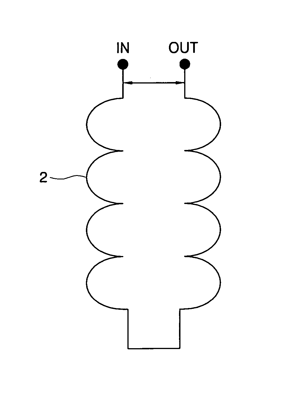
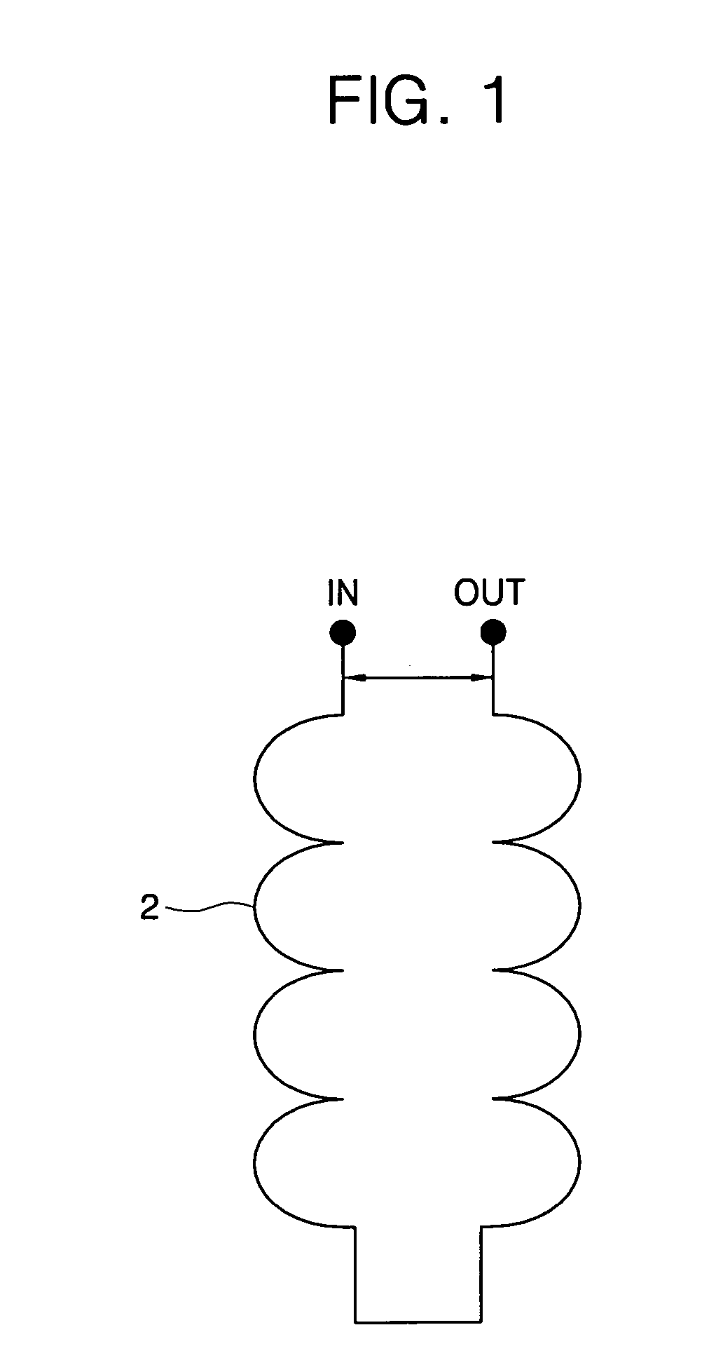
However, as shown in FIG. 1, the conventional resistive superconducting fault current limiters disclosed in '365 and '388 patents include a power input terminal IN and a power output terminal OUT, which are located at the same level, and a dielectric distance between ends of the power input and output terminals IN and OUT is very short, thereby generating disadvantages in electrical insulation.
That is, since most of the conventional resistive superconducting fault current limiters have a very short distance between first and final turns to which operational voltage is applied, they are inevitably vulnerable to the insulation.
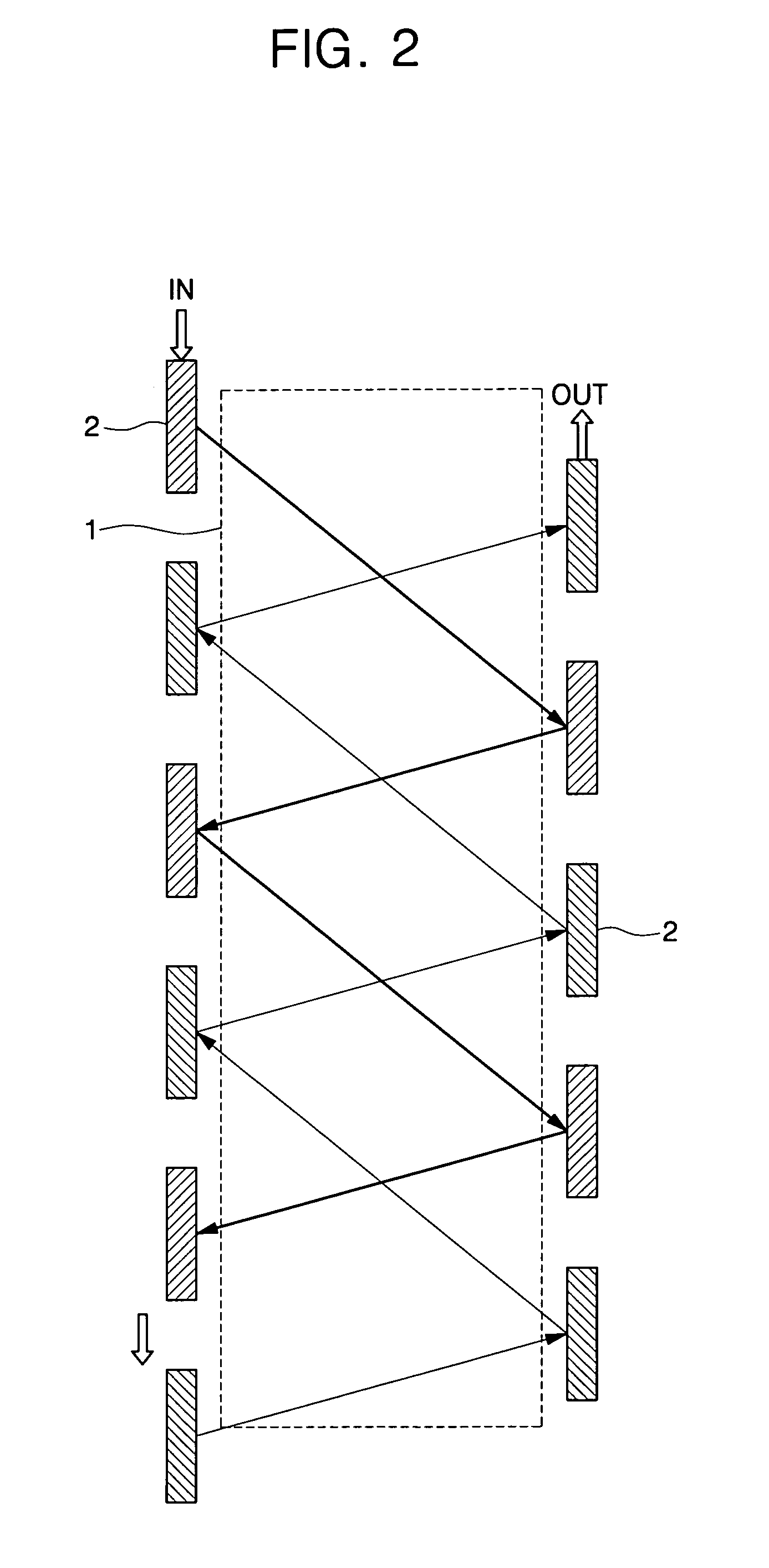
In addition, since the conventional superconducting fault current limiters have a structure that a superconducting wire or coil 2 wound around a bobbin 1 is stacked as shown in FIG. 2, a temperature may be excessively increased during the phase transition, and a recovering speed of the fault current limiter may be considerably delayed until the next fault current is limited.
However, in the case of '914 patent, since a low temperature superconducting wire of stabilizer is made of a copper alloy as a main component, the stabilizer has a disadvantage of generating a very low resistance in a quench state of escaping from the superconducting state.
Therefore, the stabilizer of '914 patent requires a very long wire.
In addition, the lower temperature superconducting wire has a circular cross-section difficult to be wound around the same frame, and though the wire is wound, a somewhat magnetic leakage flux is generated to make it difficult to expect a perfect non-induction characteristic.
Nevertheless, '914 patent has no structure capable of connecting the superconducting wire in parallel.

Method used


Image

  • Resistive superconducting fault current limiter
  • Resistive superconducting fault current limiter
  • Resistive superconducting fault current limiter

Examples


first embodiment

[0049] Referring to FIGS. 3 to 10, the resistive superconducting fault current limiter in accordance with the present invention includes a first superconducting module 10, a second superconducting module 20, and a connecting member 30.

[0050] Referring to FIGS. 3 to 5, the first superconducting module 10 is connected to an input terminal side of a power system (for example, a power transmission line) in order to stabilize insulation characteristics. The first superconducting module 10 includes a first outer bobbin 11, a first wire 12, a first inner bobbin 13, a second wire 14, a current introduction terminal 15.

[0051] Referring to FIG. 4, the first outer bobbin 11 has a predetermined diameter of cylindrical shape, and the first wire 12 is wound on a peripheral surface of the first outer bobbin 11 in one direction with a predetermined inclination angle.

[0052] The first inner bobbin 13 has a diameter smaller than that of the first outer bobbin 11, and is disposed in the first outer b...

second embodiment

[0102]FIGS. 12 and 13 illustrate the present invention, showing a plurality of wires parallelly connected to one bobbin.

[0103] That is, the second embodiment of the present invention includes the plurality of wires wound around the one bobbin, rather than using the connecting member of the first embodiment.

[0104] The current limiter of the second embodiment includes a bobbin 41 having a predetermined diameter, a first wire winding groove 42 formed on a peripheral surface of the bobbin 41 in one direction with a predetermined inclination angle, a second wire winding groove 43 formed to have a depth different from the first wire winding groove 42 through a stepped surface in the other direction with a predetermined inclination angle, an inner wire 44 wound in the first wire winding groove 42, an outer wire 45 wound in the second wire winding groove 43, an insulting material 46 formed between the inner wire 44 and the outer wire 45, a current introduction terminal (not shown) and a cu...


PUM


Abstract

Provided is a superconducting fault current limiter capable of reducing a fault current in a power application field, such as a lossless power transmission line, a superconductive magnet for generating a strong or very stable magnetic field, an energy storage, a motor, a generator, and so on, of generating or transporting a large amount of current, and a traffic application field such as a superconducting magnetic levitation train, a superconducting propulsion ship, and so on. In accordance with the present invention, after the inner bobbin is disposed in the outer bobbin, the wires are wound around the inner and outer bobbins to be connected through the current introduction terminal in directions opposite to each other to thereby constitute the superconducting module, and the module is symmetrically formed through the connecting member, thereby completing the current limiter. Therefore, it is possible to obtain a higher insulation resistance by locating an input terminal and an output terminal of the current limiter opposite to each other to stabilize insulation characteristics, though using the same length as a conventional superconducting wire. In addition, it is possible to reduce a temperature increasing width, and rapidly recovering a re-cooling speed of the current limiter.

Description

CROSS-REFERENCE TO RELATED APPLICATION [0001] This application claims the benefit of Korean Patent Application No. 10-2005-0044247, filed May 25, 2006, the disclosure of which is hereby incorporated herein by reference in its entirety. BACKGROUND OF THE INVENTION [0002] 1. Field of the Invention [0003] The present invention relates to a superconducting fault current limiter capable of reducing a fault current in a power application field, such as a lossless power transmission line, a superconductive magnet for generating a strong or very stable magnetic field, an energy storage, a motor, a generator etc., of generating or transporting a large amount of current, and a traffic application field such as a superconducting magnetic levitation train, a superconducting propulsion ship, and so on. [0004] 2. Description of the Related Art [0005] A superconducting fault current limiter, which is classified into an inductive type or a resistive type, is an electric power device for instantly g...

Claims


Application Information

Patent Timeline
IPC IPC(8): H02H7/00
CPCH01F6/06H01F27/34Y02E40/69H01L39/16H02H9/023H01F2006/001Y02E40/60H10N60/30H02H9/02
Inventor LEE, CHAN-JOOSEOK, BOK-YEOL
Owner HYUNDAI HEAVY IND CO LTD
Learn More