
Biogas producing facility with anaerobic hydrolysis

a technology of anaerobic hydrolysis and biogas, which is applied in the direction of biochemistry apparatus, gaseous fuels, biochemistry apparatus and processes, etc., can solve the problems of limited resources and high cost, and achieve the effect of reducing the required capacity, reducing investment and cost, and low operational cos

Inactive Publication Date: 2006-12-07
BIO CIRCUIT
View PDF10 Cites 31 Cited by
  • Summary
  • Abstract
  • Description
  • Claims
  • Application Information

AI Technical Summary

Benefits of technology

[0011] It is a further advantage of the present invention that no further chemicals are added to assist the anaerobic hydrolysis process.
[0012] Surprisingly, it has been found that the output of the anaerobic hydrolysis substantially does not smell.
[0013] The hydrolysis process operates effectively on various materials, such as planting stock, such as straw, fibres, and similar fibre containing materials etc, sludge, such as biological sludge from sewage treatment plants, etc, bacterial material, animal feed remains, animal remains, etc.
[0014] Preferably, the reactor is an anaerobic reactor due to its low operational cost.
[0015] In a preferred embodiment of the invention, the biogas producing facility further comprises a separator that is connected to the first reactor output for selective separation of particles larger than a predetermined threshold size from the digested waste and having an output for the separated particles that is connected to the anaerobic tank for hydrolysis of the separated large particles.
[0016] Larger particles constitute most of the biological substance and thus, the useful biological substance is separated from the material that has been digested in the first reactor for further processing in the hydrolysis tank. This further reduces the required capacity of the anaerobic tank and related interconnecting systems, which in turn further reduces investments and cost.

Problems solved by technology

There is a high demand for industrial waste for this purpose, which has made it a rather expensive and limited resource.

Method used


Image

  • Biogas producing facility with anaerobic hydrolysis
  • Biogas producing facility with anaerobic hydrolysis
  • Biogas producing facility with anaerobic hydrolysis

Examples


Embodiment Construction

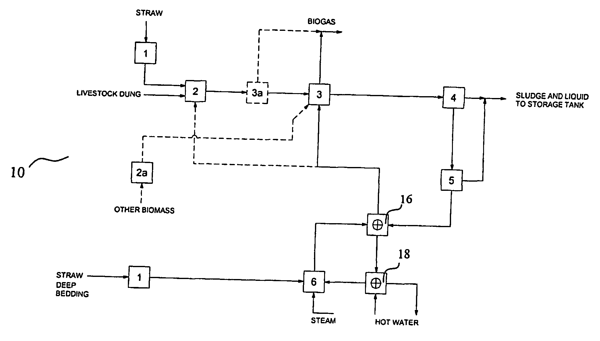
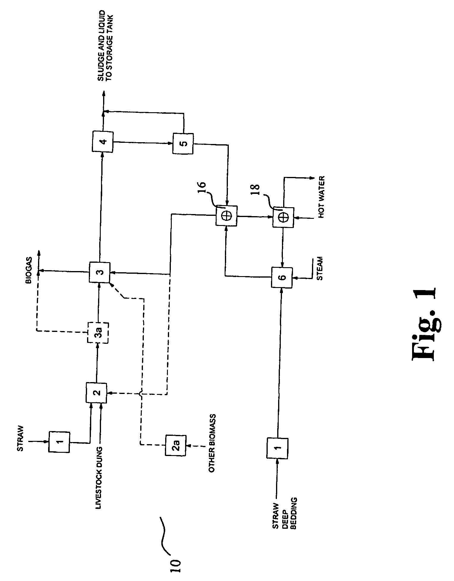
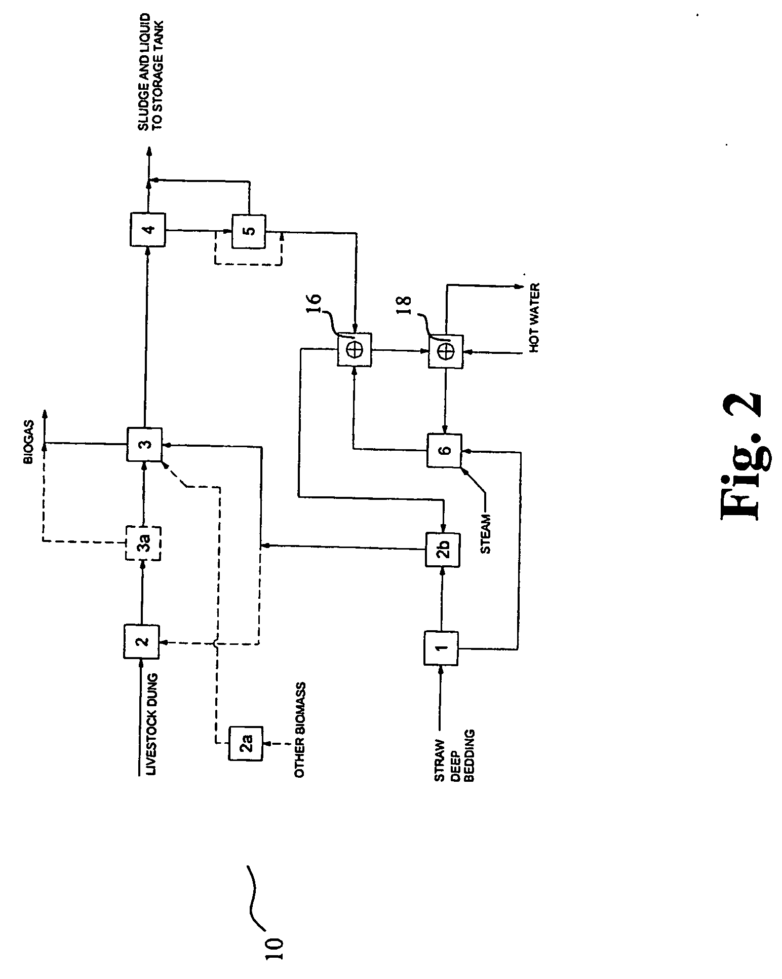
[0045]FIG. 1 schematically illustrates a biogas producing facility 10 for producing biogas from livestock dung mixed with organic waste, such as corn, grass, dry grass, fresh or dry straw, straw contained in livestock dung or in deep-bedding, silage, animal remains, etc. In the illustrated embodiment, the dung has low dry matter content so that a substantial amount of straw may be added to the dung. A partitioning device 1 cuts straw into straw parts having a mean length of approximately 5 to 10 cm. The cut straws and livestock dung are mixed in a tank 2, and the mixed matter is heat treated in a tank 3a, typically at 70-75° C., to kill unwanted bacteria. The heat-treated matter is fed into a first reactor 3 to be digested by bacteria for formation of biogas. Typically, the matter is digested for approximately 15-30 days depending on the reactor temperature. Typically, the reactor temperature ranges from 30° C.-55° C. A separator 4 separates particles larger than 0.2 cm to 2 cm, and...


PUM


Abstract

The present invention on relates to a method and a system for conversion of organic waste into biogas, i.e. a methane containing gas, with an improved efficiency and economy. The system comprises a reactor (3) for holding organic waste for production of biogas by digestion and having an output for digested waste, and an anaerobic tank (6) that is connected to the reactor (3) output for anaerobic hydrolysis of the digested waste and having an output for hydrolysed material that is connected to an input of the reactor for adding hydrolysed material to the content of the reactor. The anaerobic hydrolysis process makes the energy content of material that has not been digested in the reactor available for bacterial digestion and thus, the hydrolysed material is fed back into the reactor for further bacterial conversion into biogas.

Description

FIELD OF THE INVENTION [0001] The present invention relates to a method and a system for conversion of organic waste into biogas, i.e. a methane containing gas, with an improved efficiency and economy. BACKGROUND OF THE INVENTION [0002] Typically, today's biogas producing facilities depend on supply of industrial waste containing fat to be economically feasible. Fat has a high energy to weight ratio, which makes it a useful input for biogas producing facilities. There is a high demand for industrial waste for this purpose, which has made it a rather expensive and limited resource. [0003] Thus, there is a need for a biogas producing facility that makes it possible to substitute industrial waste with other materials, e.g. other waste materials. SUMMARY OF THE INVENTION [0004] According to the present invention, the above and other objects are fulfilled by a biogas producing facility comprising a first reactor for holding organic waste for production of biogas by digestion and having a...

Claims


Application Information

Patent Timeline
IPC IPC(8): C12M1/107C12P5/02C02F11/04
CPCC02F11/04C12M21/04Y02E50/343C12M23/58C12M47/06C12M23/36Y02E50/30
Inventor JENSEN, JANJENSEN, PREBEN
Owner BIO CIRCUIT
Learn More