BLDC motor and pump assembly with encapsulated circuit board

a technology of encapsulated circuit board and motor, which is applied in the direction of positive displacement liquid engine, pump, machine/engine, etc., can solve the problems of increasing the design and manufacturing complexity of the motor, the motor will not work normally, and the circuit will be malfunctioning, so as to improve the efficiency and/or protection of the motor, the effect of improving the responsiveness and design freedom

Active Publication Date: 2006-12-14
CARTER FUEL SYST
View PDF71 Cites 38 Cited by
  • Summary
  • Abstract
  • Description
  • Claims
  • Application Information

AI Technical Summary

Benefits of technology

[0007] The subject invention provides further advances in the BLDC motor and pump assembly technology. According to one aspect of the invention, a BLDC motor assembly comprises a housing, a shaft supported for rotation within the housing, a stator disposed within the housing for generating an electro-magnetic field, a rotor operatively coupled to the shaft and disposed for powered rotation within the stator in response to the electro-magnetic field, at least one temperature sensitive electronic device (TSED) disposed within the housing and electrically connected to the stator for controlling or measuring an aspect of the electro-magnetic field, and a fuel resistant and electrically insulated polymeric material introduced into the housing and in contact therewith while encapsulating the TSED so that the TSED is protected from adverse temperature and chemical agents without the need for a separate internal container or a pre-potting operating. The TSED, which may be carried on a printed circuit board within the housing, is thus overmolded with polymeric material so that the polymeric material fills, or substantially fills, a space within the housing. Not only is the cost and weight associated with a prior art dedicated container for the electronics eliminated, but this invention allows greater design freedom in the location or placement of the various electrical devices within the housing for better motor efficiency and / or protection. For example, a BLDC motor may typically include a Hall-effect sensor to monitor the position of the rotor. According to the invention, which obviates the need for a separate internal container for the electronics, the Hall-effect sensors can be optimally position to provide better responsiveness and in some cases even to eliminate the need for additional electromagnets mounted on the rotor.
[0008] According to another aspect of the invention, a BLDC motor assembly comprises a housing, a shaft supported for rotation within the housing, a stator disposed within the housing for generating an electro-magnetic field, a rotor operatively coupled to the shaft and disposed for powered rotation within the stator in response to the electro-magnetic field, at least one TSED disposed within the housing and electrically connected to the stator for controlling an aspect of the electro-magnetic field, the TSED having a critical temperature above which device malfunction is possible, a fuel-resistant and electrically insulating polymeric material disposed in the housing and in contact therewith while encapsulating and in direct contact with the TSED, the polymeric material being introduced into the housing in a generally fluidic form at a temperature above the critical temperature of the TSED, and a production heat sink feature located proximate the TSED to rapidly draw heat away from the TSED as the polymeric material is introduced into the housing. The production heat sink feature can be either a permanent part of the motor and pump assembly which is capable of rapidly drawing heat away from the TSED, for example the housing, or the production heat sink feature can be a removable molding core or sacrificial heat absorbing element like polystyrene. In the case of a removable molding core, further enhanced cooling characteristics can be achieved if the molding core is chilled. Thus, the TSED is protected against damage during the encapsulation process by the strategic and intentional use of a production heat sink feature.
[0009] According to yet another aspect of the invention, a BLDC motor assembly comprises a housing, a shaft supported for rotation within the housing, a stator disposed within the housing for generating an electro-magnetic field, a rotor operatively coupled to the shaft and disposed for powered rotation within the stator in response to the electro-magnetic field, at least one TSED disposed within the housing and electrically connected to the stator for controlling an aspect of the electro-magnetic field, the TSED having a critical temperature above which device malfunction is possible; a fuel-resistant and electrically insulating polymeric disposed in the housing and in contact therewith while encapsulating and in direct contact with the TSED, and a fluid flow passage extending through the housing and routing adjacent the TSED for convectively removing heat from the encapsulated TSED by the movement of fluid at a temperature below the critical temperature to prevent device malfunction. This aspect of the invention, which can be conveniently realized when incorporated with a fluid pumping device, such as a fuel pump, takes advantage of the natural convective effects of a moving stream of cool liquid to pull heat away from the TSED during operation, thereby helping to maintain its operating temperature below the critical temperature.

Problems solved by technology

While prior art BLDC motor designs have achieved their intended purpose, problems still exist.
For example, the addition of control circuitry within the motor has increased design and manufacturing complexity of the motor.
If the fluid contacts the control circuitry corrosion and malfunctioning of the circuit will occur.
The control circuitry includes temperature sensitive components that may be damaged by excessive heat applied during either the manufacturing of the motor or operation of same.
Furthermore, the control circuitry is susceptible to radiated emissions from surrounding electrical devices.

Method used


Image

  • BLDC motor and pump assembly with encapsulated circuit board
  • BLDC motor and pump assembly with encapsulated circuit board
  • BLDC motor and pump assembly with encapsulated circuit board

Examples


Embodiment Construction

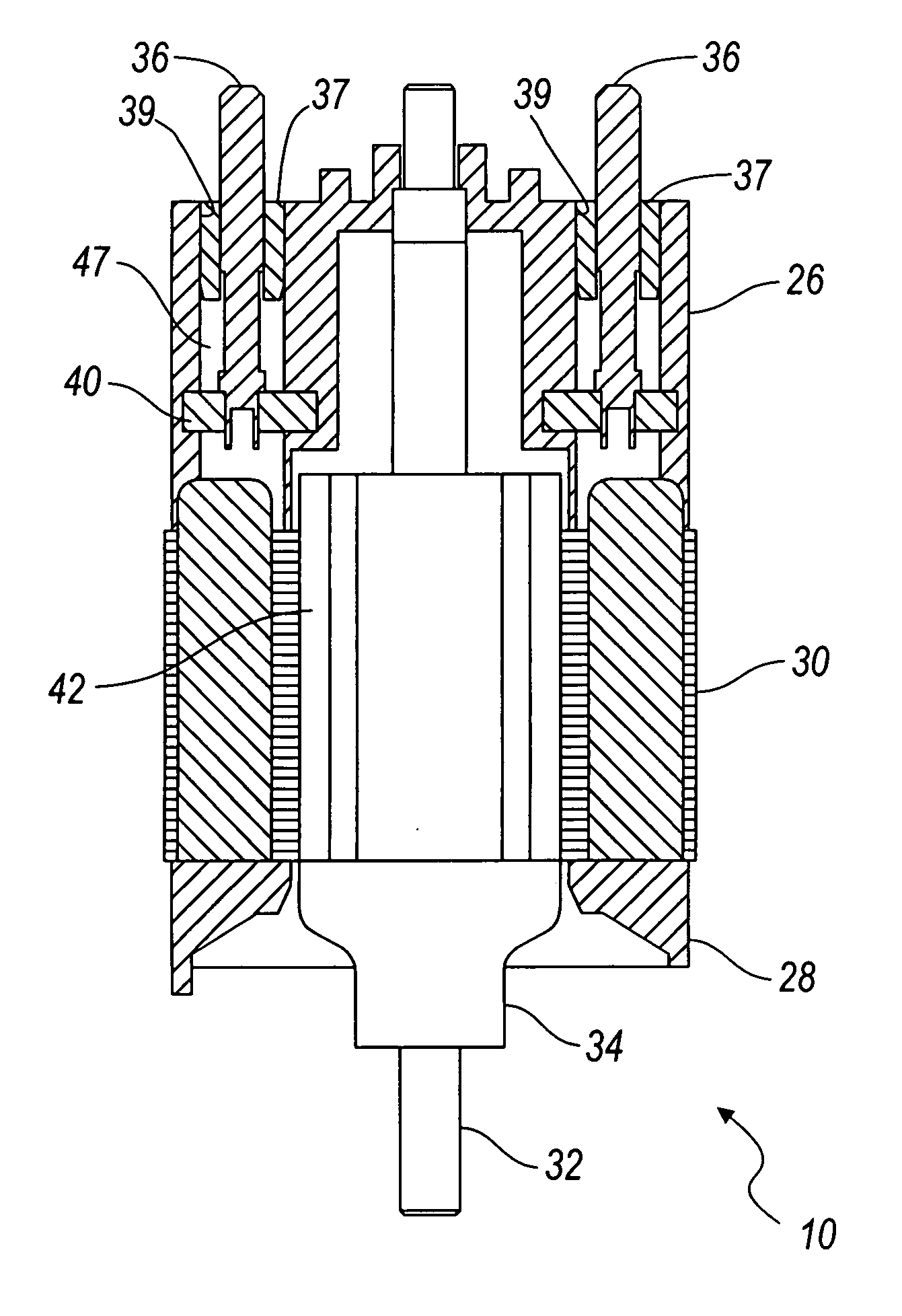
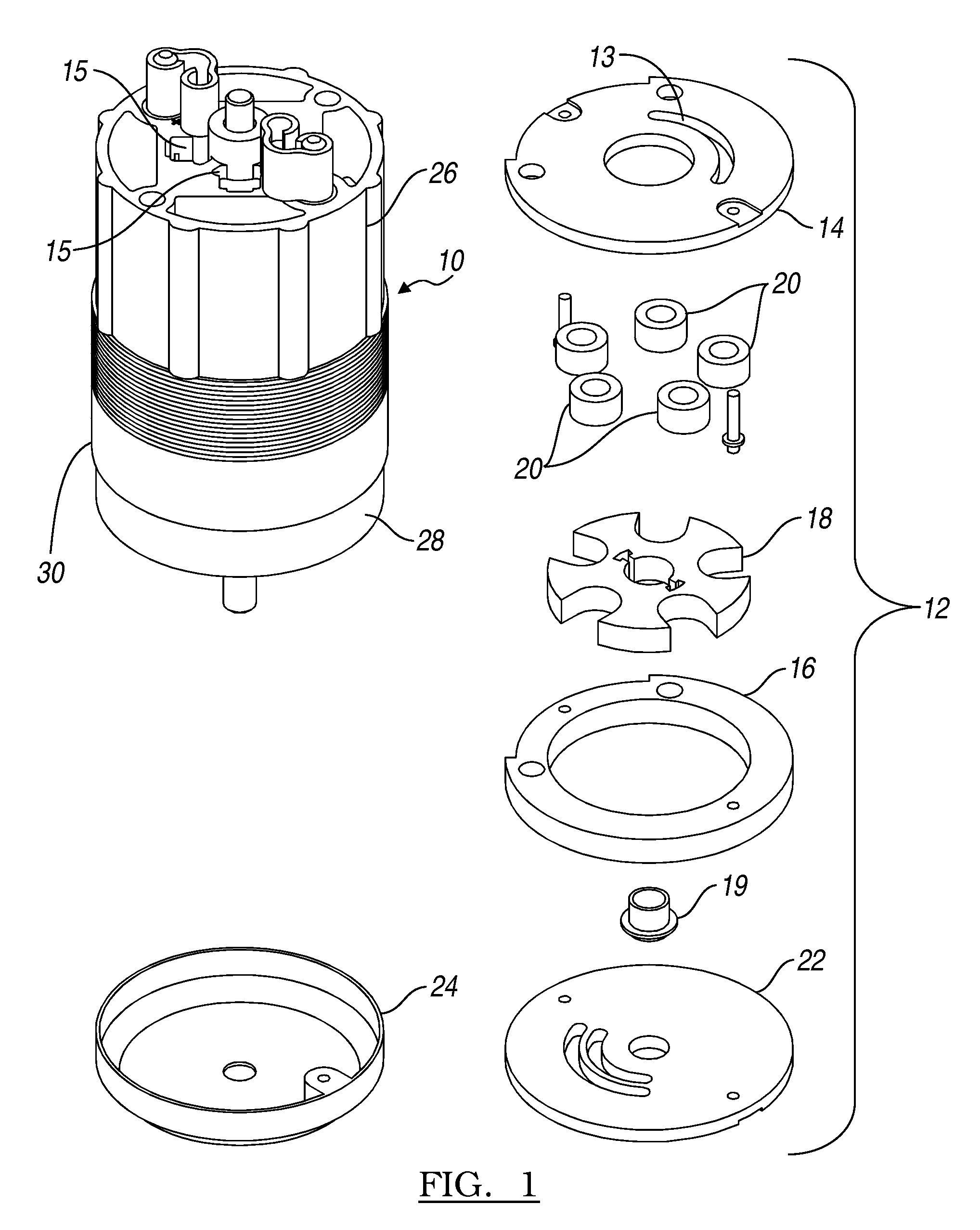
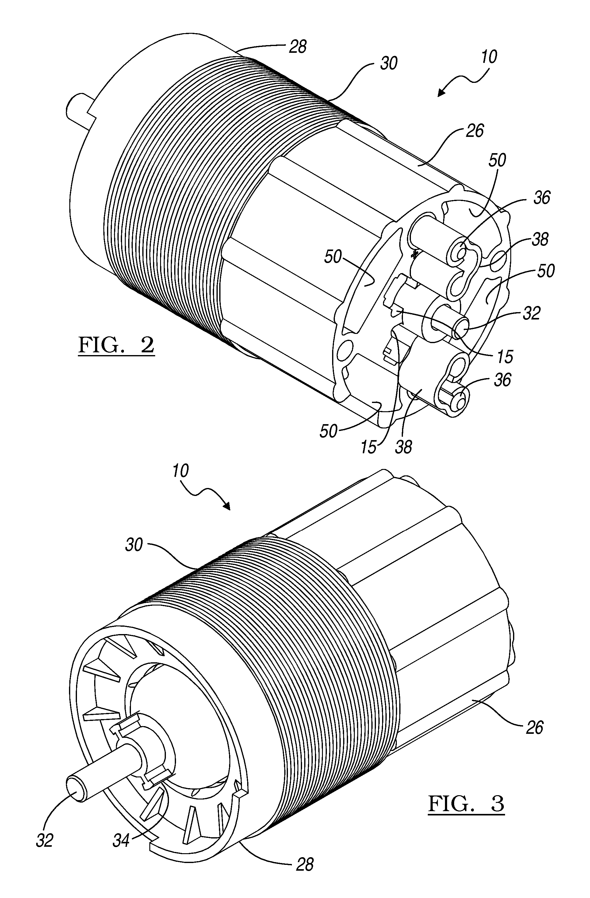
[0022] Referring to the Figures, wherein like numerals indicate like or corresponding parts throughout the several views, a brushless direct current (BLDC) motor assembly according to an embodiment of the present invention is generally shown at 10.

[0023] In FIG. 1, the motor assembly 10 is illustrated in the application of a fuel pump. A fluid pump, generally shown at 12, is coupled to the lower end of the motor assembly 10. However, any other driven component or feature can of course be coupled to the motor assembly 10 instead of a fuel pump. The fluid pump 12 is shown here of the vane style, however, other pump types, such as other positive displacement styles, impeller styles, and the like, may be used with equal effect.

[0024] In FIG. 1, the fluid pump 12 is shown including an outlet port plate 14 which adjoins to the lower end of the motor assembly 10. A cam ring 16 is held against the outlet port plate 14 and surrounds a rotor 18 and an array of captured rollers 20. The rotor...


PUM


Abstract

A BLDC motor assembly and method for manufacturing same is disclosed. The motor has a housing, a shaft supported for rotation within the housing, a stator disposed within the housing for generating an electro-magnetic field, a rotor operatively coupled to the shaft and disposed for powered rotation within the stator in response to the electro-magnetic field, at least one temperature sensitive electronic device (TSED) disposed within the housing and electrically connected to the stator for controlling or measuring an aspect of the electro-magnetic field, and a fuel resistant and electrically insulated polymeric material encapsulating the TSED so that the TSED is protected from adverse temperature and chemical agents without the need for a separate internal container or a pre-potting operating. The TSED, which may be carried on a printed circuit board within the housing, is thus overmolded with polymeric material so that the polymeric material fills, or substantially fills, a space within the housing. Not only is the cost and weight associated with a prior art dedicated container for the electronics eliminated, but this invention allows greater design freedom in the location or placement of the various electrical devices within the housing for better motor efficiency and/or protection.

Description

CROSS-REFERENCE TO RELATED APPLICATION [0001] The present application claims priority to U.S. provisional application entitled BLDC Motor and Pump Assembly with Encapsulated Circuit Board having Ser. No. 60 / 681,795 and filed on May 17, 2005.BACKGROUND OF THE INVENTION [0002] 1. Field of the Invention [0003] The invention relates generally to a brushless direct current motor, and more particularly to a motor coupled to a fluid pump having electronic components and circuitry encapsulated in a polymeric material. [0004] 2. Related Art [0005] With the introduction of electronic control systems for electric motors, the industry objectives of long life, efficiency, reliability and low EM interference have become achievable. This is in part due to the advent of brushless direct current (BLDC) motor technology. Not only are the problems once associated with the prior art permanent magnet direct current motors overcome, but advances in MOS-FET devices have led to further performance advantag...

Claims


Application Information

Patent Timeline
Patent Type & Authority Applications(United States)
IPC IPC(8): H02K5/12H02K5/10H02K13/00H02K11/00H02K23/66
CPCH02K5/12H02K5/225H02K15/14H02K11/0047H02K11/0073H02K11/0021H02K11/215H02K11/25H02K11/33F04B17/04F04B35/04H02K11/00
Inventor ACHOR, KYLE D.MAHONEY, DANIEL L.
Owner CARTER FUEL SYST
Why Eureka
Try Eureka