Supercharge Your Innovation With Domain-Expert AI Agents!

Ramped RF acousto-optic Q-switch driver

a technology of acousto-optic qswitch and ram, which is applied in the direction of optics, laser details, instruments, etc., can solve the problems of poor laser performance, severe temperature gradients within the laser resonator, and loss of intra-cavity, and achieve high optical transparency and acoustic figure of merit

Inactive Publication Date: 2006-12-14
HONEYWELL INT INC
View PDF9 Cites 0 Cited by
  • Summary
  • Abstract
  • Description
  • Claims
  • Application Information

AI Technical Summary

Benefits of technology

[0026] The present invention includes a device and method for driving a transducer of an acoustooptical Q-switch. The transducer is configured to selectively propagate acoustic waves in an acoustooptical deflection material. Optimally, the media exhibits a high acoustic figure of merit, which is a function of its material properties as well as high optical transparency at the laser wavelength. The device includes a signal generator that has an input. The signal generator is configured to output a sine wave to d

Problems solved by technology

The acoustooptic deflection material, when excited by a transducer in communicative contact with the acoustooptic deflection material, exhibits a diffraction effect on the intracavity laser output and diffracts part of the beam out of the cavity alignment, resulting in intra-cavity loss.
The heating effect can cause severe temperature gradients within the laser resonator.
These gradients can cause additional intra-cavity loss resulting in poorer laser performance.

Method used


Image

  • Ramped RF acousto-optic Q-switch driver
  • Ramped RF acousto-optic Q-switch driver
  • Ramped RF acousto-optic Q-switch driver

Examples


Embodiment Construction

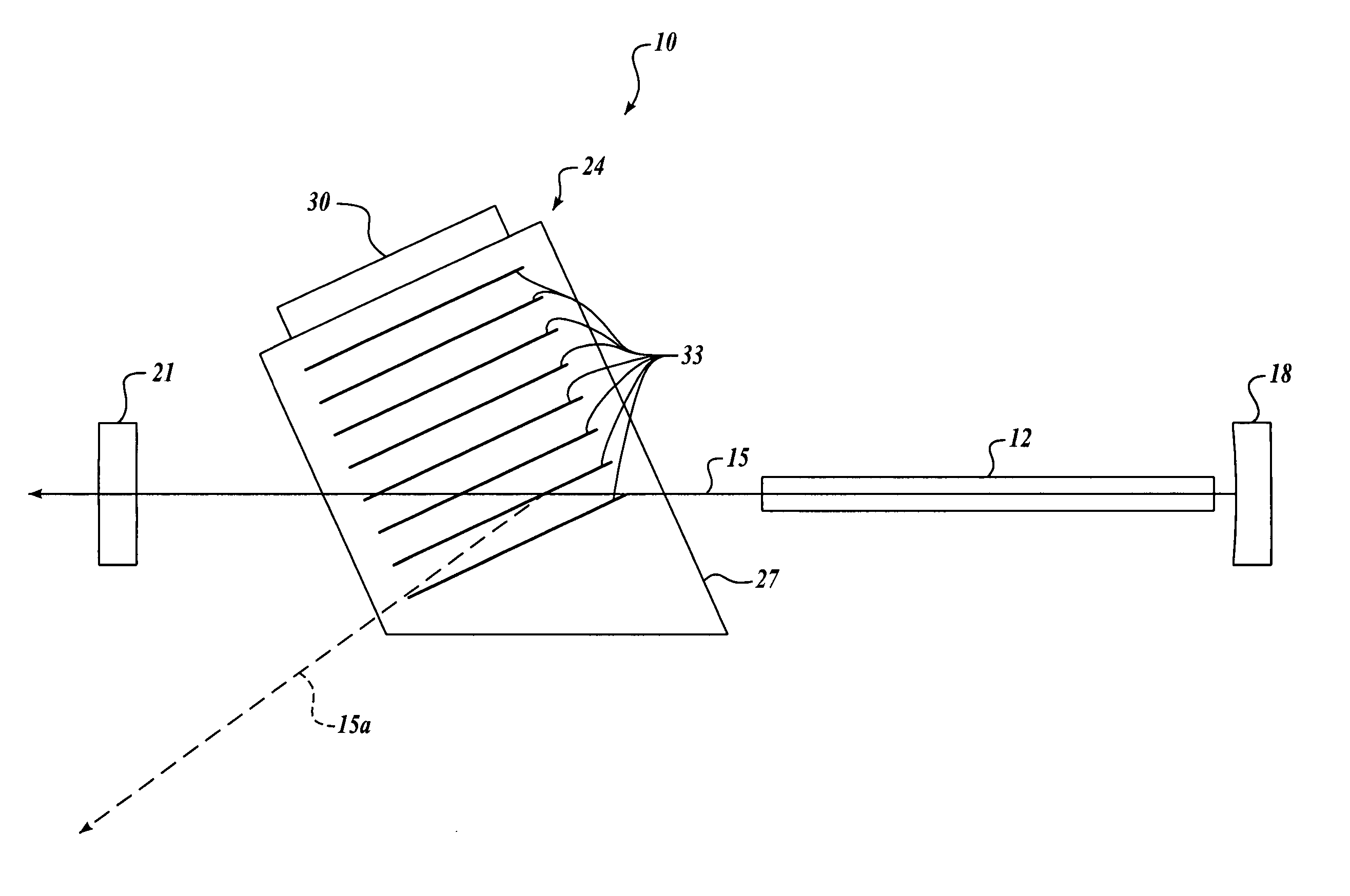
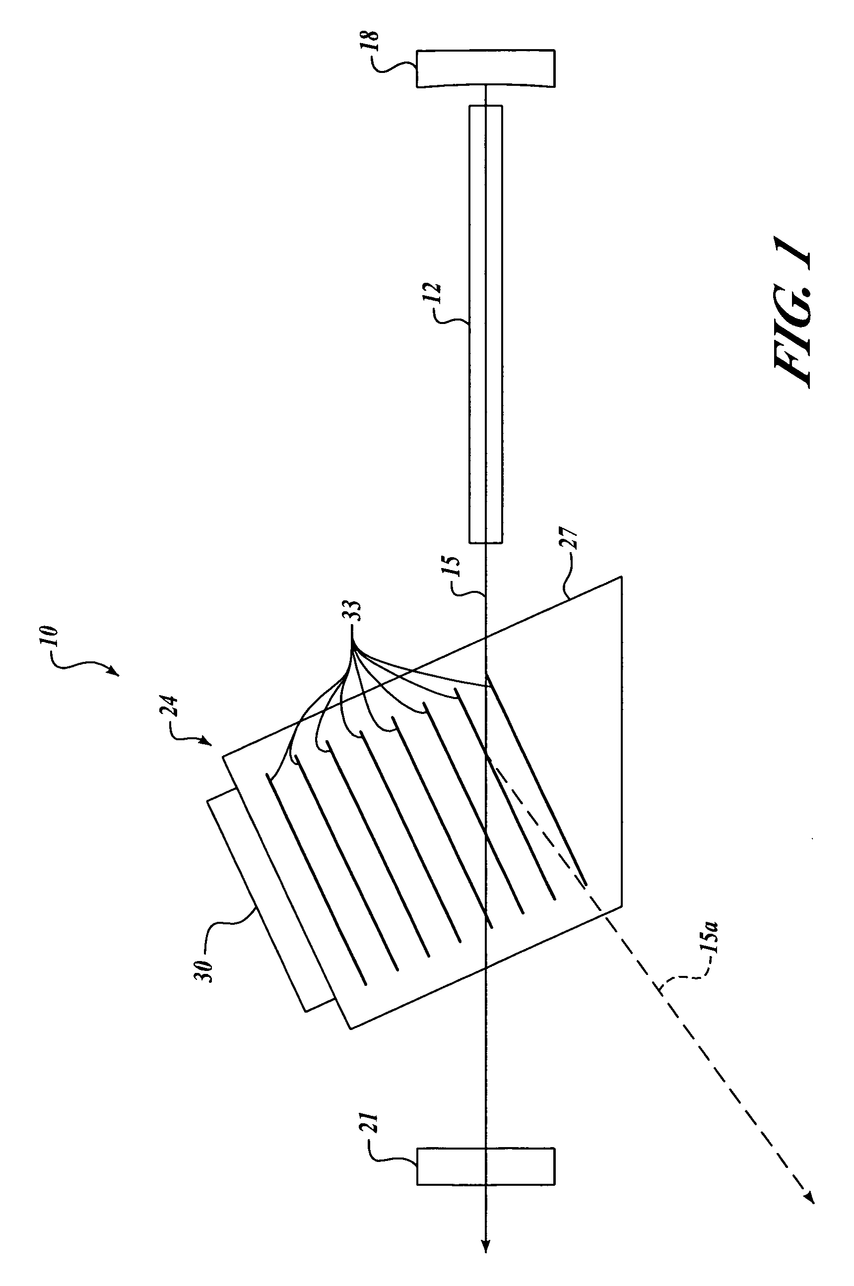
[0037] Referring to FIG. 1, the purpose of an acoustooptical Q-switch 24 is to create a sufficiently high loss within the laser resonant cavity to allow energy to be stored in the laser material 12 until an output pulse is desired. RF power applied to a transducer 30 in operative communication with the acoustooptical deflection material 27 diffracts some portion of a laser beam 15 within the medium. Upon reducing the RF drive power, the laser signal builds up from noise. This noise signal evolves into a high amplitude laser pulse since the system 10 gain is now greater than the system 10 loss.

[0038] Depending upon conditions, that diffraction can be primarily a single beam (Bragg Condition), or multiple beams (Raman-Nath condition). In any case, the diffracted beam causes the energy of the incident laser beam 15 to fall outside of the resonant cavity thereby creating loss. That loss is generally proportional to input RF power and related to physical construct, material parameters, ...


PUM


Abstract

A device and a method for driving a transducer of an acoustooptical Q-switch. The device includes a signal processor that has an input. The signal processor is configured to output a sine wave to drive the transducer at a frequency selected to create a standing acoustic wave in the acoustooptical deflection material. The standing acoustic wave is configured to diffract an incident beam and has an amplitude based upon a signal at the input. A control wave generator is configured to generate a control signal at the input. The control signal is a function of a selected ratio relating an energy of the incident beam to an energy of a diffracted beam within the Acoustooptical Q-switch.

Description

PRIORITY CLAIM [0001] This is a utility application based on U.S. provisional application No. 60 / 675,357 filed Apr. 27, 2005 and incorporated herein by reference. BACKGROUND OF THE INVENTION [0002] Q-Switching is a mode of operating a laser in which energy is stored in the laser material during pumping in the form of atoms in the excited state in the upper laser level and suddenly released in a single, short burst. A highly simplistic view of a laser cavity includes a gain medium between collimated mirrors. Q-switching refers to generating short high intensity pulses out of lasers by modulating the Q of a resonator cavity from a high loss to low loss condition. [0003] Examples of such elements that can serve as effective modulators are acoustooptic devices, electro-optic devices, passive saturable units, and spinning mirrors. Each of these elements trade off characteristics with respect to efficiency, size, thermal environmental behavior, optical damage limits, ease of alignment and...

Claims


Application Information

Patent Timeline
IPC IPC(8): G02F1/11
CPCH01S3/117H01S3/1306H01S3/1305
Inventor RAPOPORT, WILLIAM R.VETORINO, STEVEN
Owner HONEYWELL INT INC
Features
  • R&D
  • Intellectual Property
  • Life Sciences
  • Materials
  • Tech Scout
  • Unparalleled Data Quality
  • Higher Quality Content
  • 60% Fewer Hallucinations
Learn More