Optical access network system

a network system and optical access technology, applied in the field of optical access network systems, can solve the problems of optical signal waveform distortion, waveform distortion, signal waveform deterioration, etc., and achieve the effect of correcting waveform distortion

Inactive Publication Date: 2006-12-14
HITACHI LTD
View PDF2 Cites 29 Cited by
  • Summary
  • Abstract
  • Description
  • Claims
  • Application Information

AI Technical Summary

Benefits of technology

[0029] More specifically, in the optical access network system of the present invention, the equalizer comprises, for example, a filter unit including a plurality of variable gain amplifiers for receiving, as optical-to-electrical converted tap signals with different delays, a signal received from said subscriber connection apparatus, a discriminator for discriminating a signal output from the filter unit, and a tap gain controller for performing adaptive gain control of each of said variable gain amplifiers according to a difference between input and output signals of said discriminator and said tap signals input to the variable gain amplifiers, and the tap gain controller includes a parameter register for setting the initial values of tap gains given from the equalizer controller to the variable gain amplifiers as initial values. In this configuration, by holding in the parameter register, during operation of the tap gain controller, latest gain values of said amplifiers under adaptive control instead of said initial values, the equalizer controller can fetch the present values of the tap gains from the parameter register.
[0030] According to the optical access network system of the present invention, since the central office side apparatus is equipped with an equalizer of the tap gain adaptive control type to correct waveform distortions of signals received from the subscriber connection apparatuses and a equalizer controller, an optimum equalization characteristic for correcting the waveform distortions of received signals can be obtained by properly switching the tap gains of the equalizer according to the transmission period of each slave station.
[0031] In the case where the present values of the tap gains have been fetched from the equalizer and stored as new initial values of the tap gains in association with the identifier of the subscriber connection apparatus that has completed data transmission, the adaptive control of the equalizer can be restarted from an optimum state upon switching the tap gains.

Problems solved by technology

However, a problem associated with the PON system using an optical fiber and a plurality of branch optical fibers as its transmission path is deterioration of signal waveforms due to optical dispersion along the optical fibers.
However, if the value of dispersion is not negligible, waveform distortions occur in optical signals.
If the value of dispersion is great and the distance of optical signal propagation is extremely long, there is a possibility that the waveform is distorted to a degree that received data becomes indiscriminative at the master station.
Consequently, when upstream packets arrive at the master station, there is a possibility that adjacent pulse waveforms overlap together and it becomes hard for the master station to correctly discriminate a 100 ps wide pulse from a pulse sequence received.
In future, if the transmission rate will rise to, e.g., 10 Gbps or higher to further speed up an optical access network, or if a signal light in a 1.5 μm band in which dispersion is inevitable will be used as a wavelength for upstream communication, the same problem as described above will occur.
However, an optical device for variable dispersion compensation enabling such a high-speed control does not achieve on a practical level as it is now.
In this case, dispersion compensators as many as the number of slave stations are required and, as a result, the system cost increases.

Method used


Image

  • Optical access network system
  • Optical access network system
  • Optical access network system

Examples


first embodiment

[0086]FIG. 8 shows a control sequence of a first embodiment of switching the equalization characteristic.

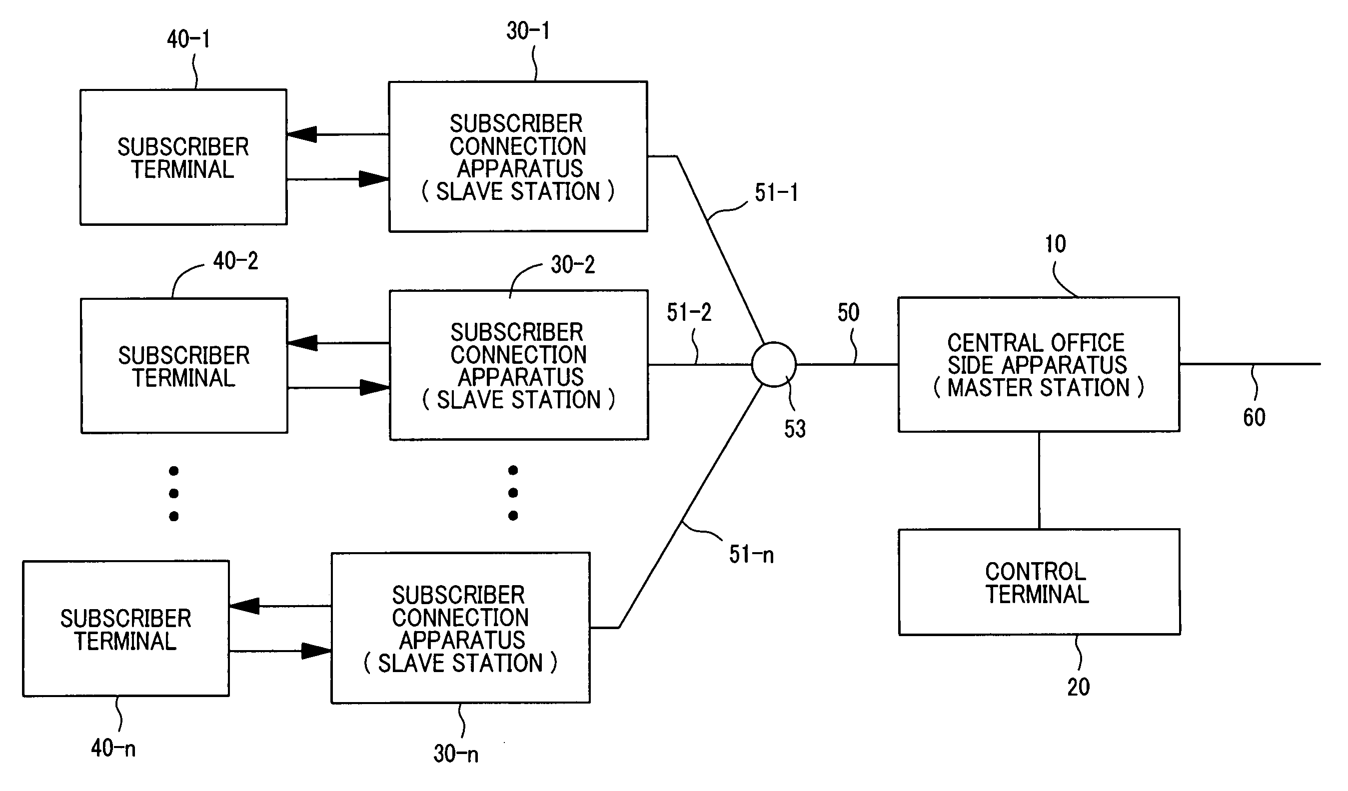
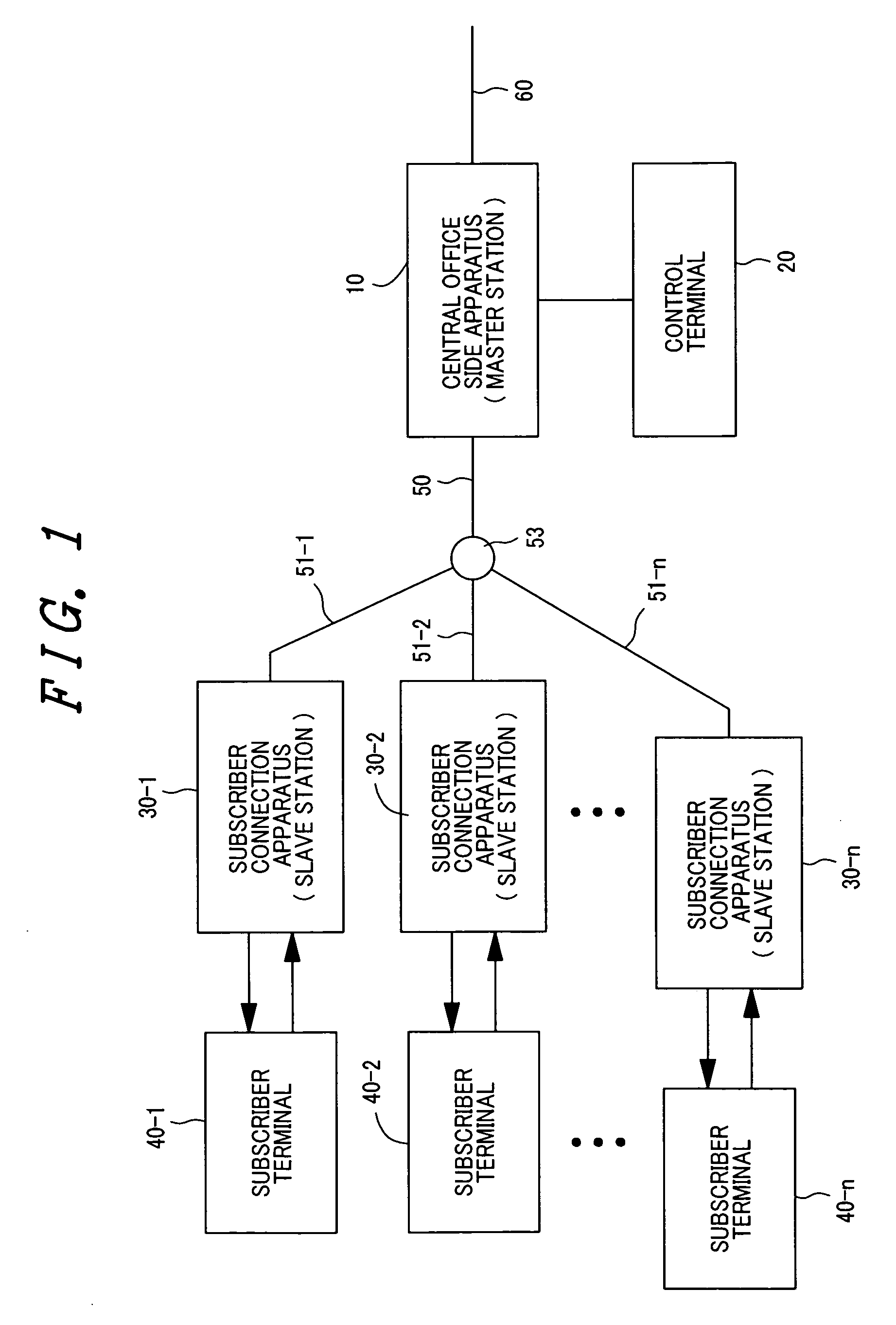
[0087] For example, a slave station 30-1 that wants to transmit data issues a transmission request to the master station 10 (401) before transmitting actual data. The data transmission request is received by the upstream frame terminating unit 113 and transferred to the main controller 100 in the master station 10. The main controller 100 determines a transmission grant period, during which no collision with upstream packets from the other slave station will occur, by referring to the timing management table 105 and taking account of a delay time of transmission signal from the slave station 30-1 specified in the delay time table 104, and assigns that period to the requester slave station 30-1 (402). Although the transmission grant period is assumed to be specified as a transmission start time T1s and a transmission end time T1e in the description herein, it may be designated as...

second embodiment

[0097]FIG. 10 shows a control sequence of a second embodiment of equalization characteristic switchover.

[0098] A feature of the second embodiment resides in that the equalizer controller 130 searches the parameter table 140 for a set of parameters (tap gain values) for the next slave station after the equalizer controller 130 fetches the converged values of the tap gains from the parameter register 80 provided in the tap gain controller 71A (71B) of the equalizer 112 and stores these values into the parameter table 140 (408), and sets the retrieved parameters to the parameter register 80 (410). In this case, an internal control delay time td, which will be elapsed until new parameters (tap gain values) for the parameter register 80 are set after the equalizer controller 130 receives a switchover request from the main controller 100, is longer than the corresponding delay time td for the first embodiment.

[0099] In the second embodiment, the main controller 100 calculates directive ...

third embodiment

[0104]FIG. 12 shows a control sequence of a third embodiment of switching the equalization characteristic.

[0105] A feature of the third embodiment resides in that the main control unit 100 issues a switchover request 405 for switching the equalization characteristic to the equalizer controller 130 at once without calculating the directive timing T1C, after the main control unit 100 notifies the requester slave station of a transmission grant period, and the equalizer controller 130 determines the timing to set parameters to the parameter register 80. In this case, the main controller 100 designates information required for the equalizer controller 130 to determine the timing to set parameters by the switchover request 405.

[0106] In this embodiment, the switchover request 405 includes the transmission start time T1s assigned to the slave station by the master station and the transmission delay time tf1 of signals transmitted from the slave station in addition to the slave station I...


PUM


Abstract

An optical access network system having a function of correcting upstream signal waveform distortions occurring in the PON section, wherein a central office side apparatus comprises a main controller to notify each subscriber connection apparatus of a transmission grant period, an equalizer of a tap gain adaptive control type to correct waveform distortions of signals received from the subscriber connection apparatuses, an equalizer controller, and a parameter table for storing, for each subscriber connection apparatus, the initial values of tap gains to be set for the equalizer. The main controller issues a switchover request for switching the equalization characteristic to the equalizer controller each time notifying a subscriber connection apparatus of a transmission grant period, and the equalizer controller retrieves the initial values of the tap gains for the subscriber connection apparatus from the parameter table in response to the switchover request, and sets these values to the equalizer.

Description

CLAIM OF PRIORITY [0001] The present application claims priority from Japanese application serial No. 2005-167764, filed on Jun. 8, 2005, the content of which is hereby incorporated by reference into this application. BACKGROUND OF THE INVENTION [0002] (1) Field of the Invention [0003] The present invention relates to an optical access network system and, more particularly, to an optical access network system where a passive optical network (PON) connects a central office side apparatus and a plurality of subscriber connection apparatuses connected to subscriber terminals and each subscriber connection apparatus transmits data during a transmission grant period assigned from the central office side apparatus. [0004] (2) Description of Related Art [0005] Recently, higher speed access networks have been developed, required by the proliferation of Internet and an expanding demand for service of access to a huge volume of data such as video streams to be delivered. As measures for provi...

Claims


Application Information

Patent Timeline
Patent Type & Authority Applications(United States)
IPC IPC(8): H04J14/00H04B10/00H04B10/07H04B10/2507H04B10/2525H04B10/27H04B10/272H04J14/08
CPCH04B10/2507H04B10/272H04J3/1694H04L2025/03668H04L25/03038H04L2025/03356H04L2025/03477H04L12/66
Inventor SEKINE, KENROTAJIMI, NOBUAKI
Owner HITACHI LTD
Why Eureka
Try Eureka