Force sensor system for use in monitoring weight bearing

a sensor system and weight bearing technology, applied in the field of ergonomically designed force sensor systems, can solve the problems of spastic drop-foot, very thin sensor arrays, and low efficiency of health care, and achieve the effect of improving the quality of neurological rehabilitation

Inactive Publication Date: 2006-12-14
ANDANTE MEDICAL DEVICES
View PDF24 Cites 97 Cited by
  • Summary
  • Abstract
  • Description
  • Claims
  • Application Information

AI Technical Summary

Benefits of technology

[0015] The present invention is an ergonomically designed force system for monitoring of weight and for activating an electronic orthosis. The system includes three independent pneumatic components that measure loads around different parts of the body. The first component is an inflatable Foot Sensor System (FSS) that is worn inside the shoe. The second component is an inflatable Knee Force System (KFS) that is worn on th

Problems solved by technology

The economic burden associated with stroke is estimated to be more than $30 billion in health care costs and lost productivity each year, making stroke one of the most expensive illnesses in the United States (Chae et al., “Neuromuscular Stimulation for Motor Relearning in Hemiplegia.
Hemiparesis due to stroke often results in spastic drop-foot (i.e., the loss of ability to dorsiflex the foot on the affected side).
The sensors which measure mechanical deformation of structural elements supporting the wearer's foot by use of electrical wire or ribbon type strain gauges accurately measure weight, but they are also disadvantageous because of their bulk and weight.
This system is disadvantageous in that the relative position of each sensor must be separately determined for each person on which the sensor is used.
These sensor arrays

Method used


Image

  • Force sensor system for use in monitoring weight bearing
  • Force sensor system for use in monitoring weight bearing
  • Force sensor system for use in monitoring weight bearing

Examples


Embodiment Construction

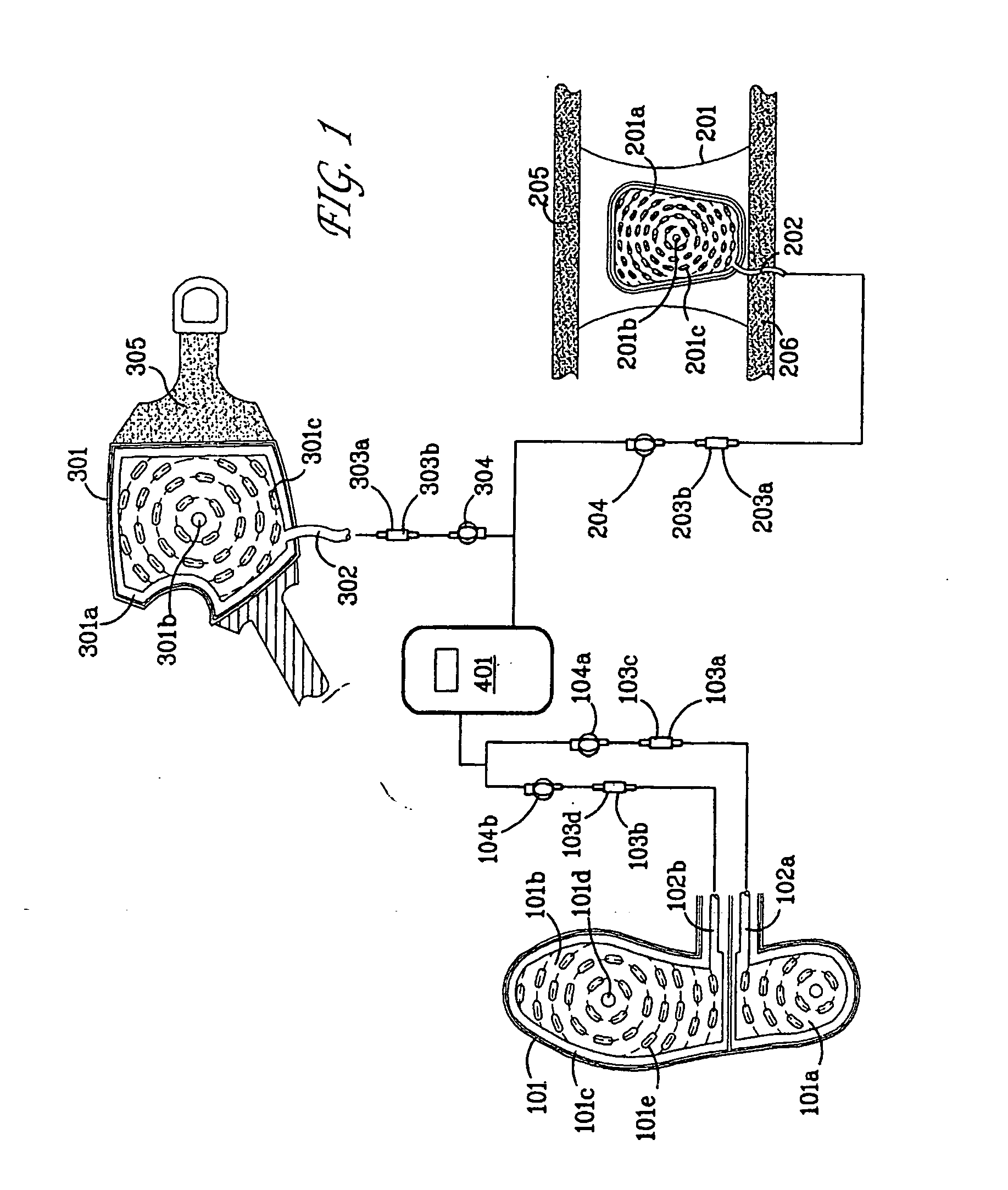
[0032] A system which meets the above-mentioned objects and provides other beneficial features in accordance with the presently preferred exemplary embodiment of the invention will be described below with reference to FIGS. 1-6. Those skilled in the art will readily appreciate that the description given herein with respect to those figures is for explanatory purposes only and is not intended in any way to limit the scope of the invention. Throughout the description, like reference numerals will refer to like elements in the respective figures.

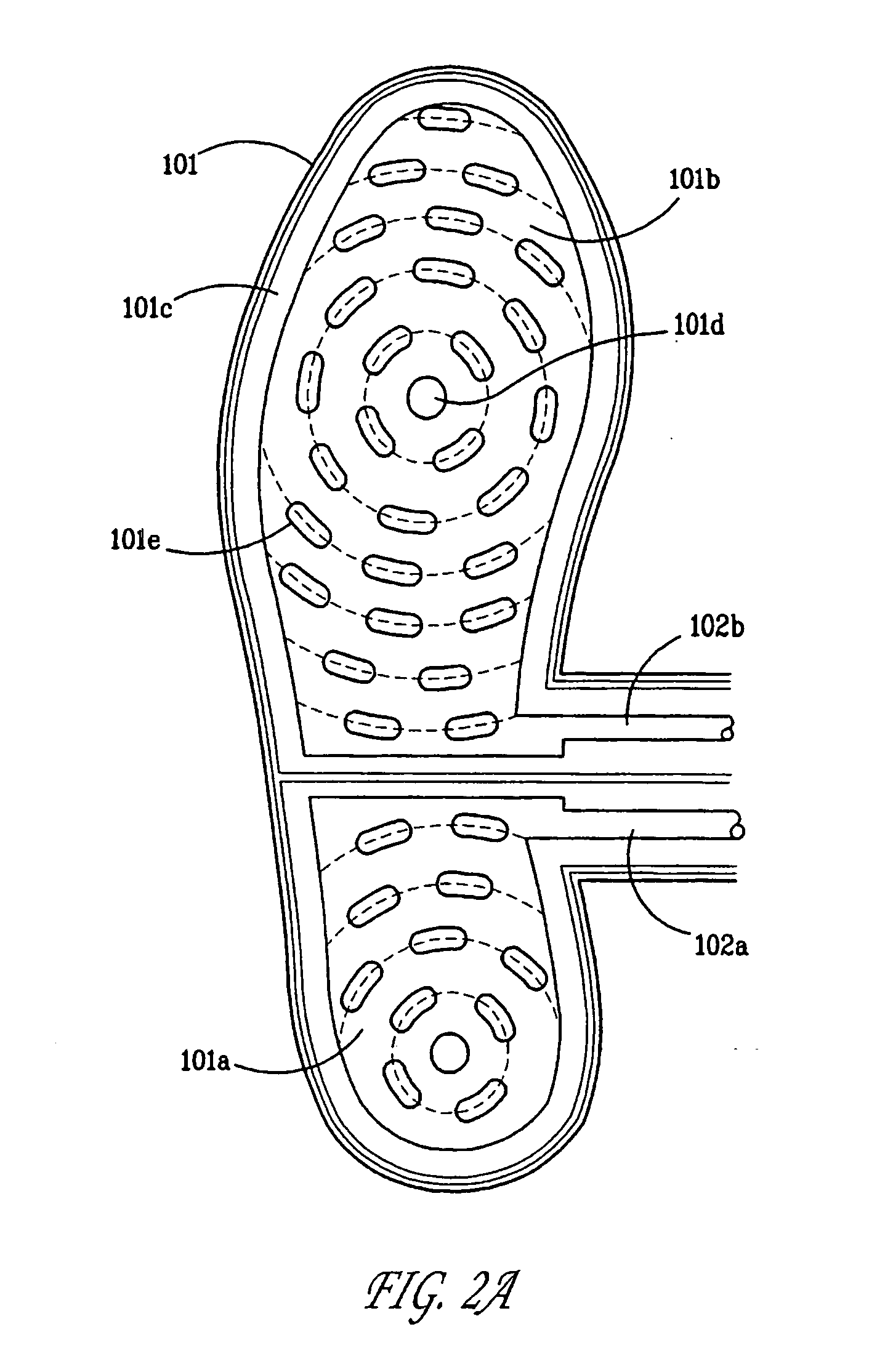
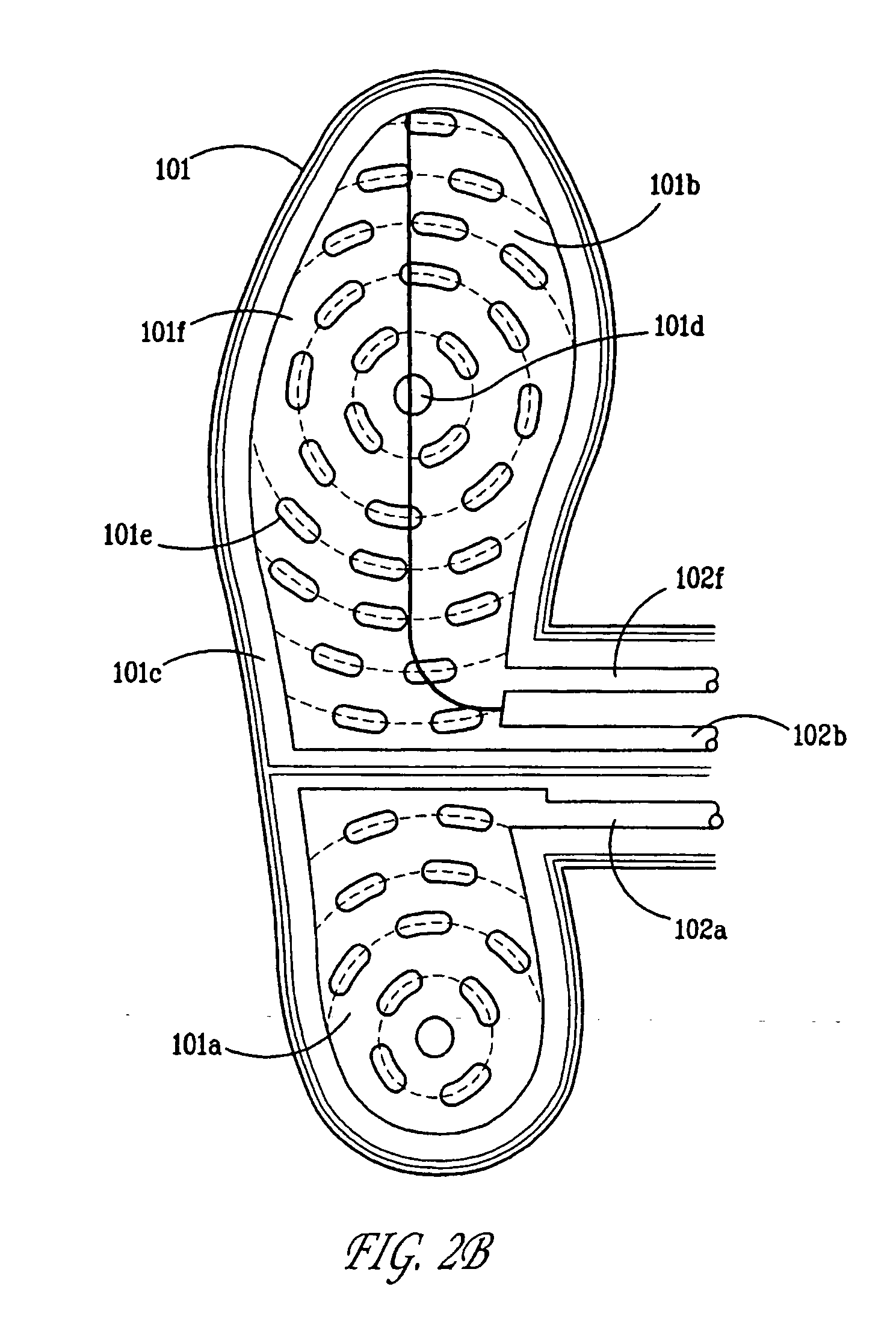
[0033] Generally, the force sensor system comprises at least one of a foot force sensor, a palm force sensor, and a knee force sensor. Each of these individual sensors convert received pressure signals into electrical output signals representative of weight bearing on a location. The electrical output signals serve as input signals to an attached control unit of a weight bearing biofeedback system or an electrical stimulation system. Referring...


PUM


Abstract

A force sensor system for use in monitoring weight bearing on a location. The force sensor system comprises at least one a foot force sensor, a palm force sensor, and a knee force sensor. The foot force sensor comprises a flexible insole containing a plurality of inflatable pockets that are inflated with air or liquid. The palm force sensor and knee force sensor each comprise a wrap to be worn around the palm and knee, respectively. Each wrap comprises a pocket. Each pocket is connected to a tube that, in turn, connects with a pressure sensor and a connector coupling that is remote from the pocket. Each coupling contains a valve. The valve opens to allow inflation and deflation of each inflatable pocket. The pressure sensors measure the air or liquid pressure within each of the inflatable pockets, and convert the corresponding pressure signal into a suitable output signal medium, usually electrical signals. The output signal from the sensors provides accurate real time input data to a weight bearing biofeedback system or to control a stimulator for activation of an electronic orthosis to normalize dynamic gait patterns.

Description

BACKGROUND OF THE INVENTION [0001] 1. Field of the Invention [0002] The present invention relates to an ergonomically designed force sensor system suitable for monitoring weight bearing or temporal parameters on different body regions, such as the foot, knee, and palm. The sensor system may be used in a weight bearing biofeedback system or a functional electrical stimulation system. The foot sensor system may be connected to a portable control unit including a weight bearing program for neurologic, orthopedic or pediatric gait rehabilitation and / or used in connection with a two channel peroneal stimulator for controlling the lower leg muscles to normalize dynamic walking patterns. On the other hand, the knee and palm sensor systems may be used in a weight bearing feedback system in physical stimulation of neurologic and pediatric injuries or for controlling an electronic orthosis. [0003] 2. Description of the Prior Art [0004] Stroke is the leading cause of disability in the elderly ...

Claims


Application Information

Patent Timeline
IPC IPC(8): A61B5/103A61B5/117A43B13/20A61B5/11A61B5/22A61F5/14A61H1/02G01L
CPCA61B5/1036A61B5/22A61B5/4528A61N1/36003A61B5/6828A61B2562/164A61B2562/168A61B5/6825
Inventor AVNI, ARIKBAR-NES, LIORFRIDEMAN, RONIT
Owner ANDANTE MEDICAL DEVICES
Why Eureka
Try Eureka