
Particulate prevention in ion implantation

Active Publication Date: 2006-12-21
AXCELIS TECHNOLOGIES
View PDF5 Cites 19 Cited by
  • Summary
  • Abstract
  • Description
  • Claims
  • Application Information

AI Technical Summary

Benefits of technology

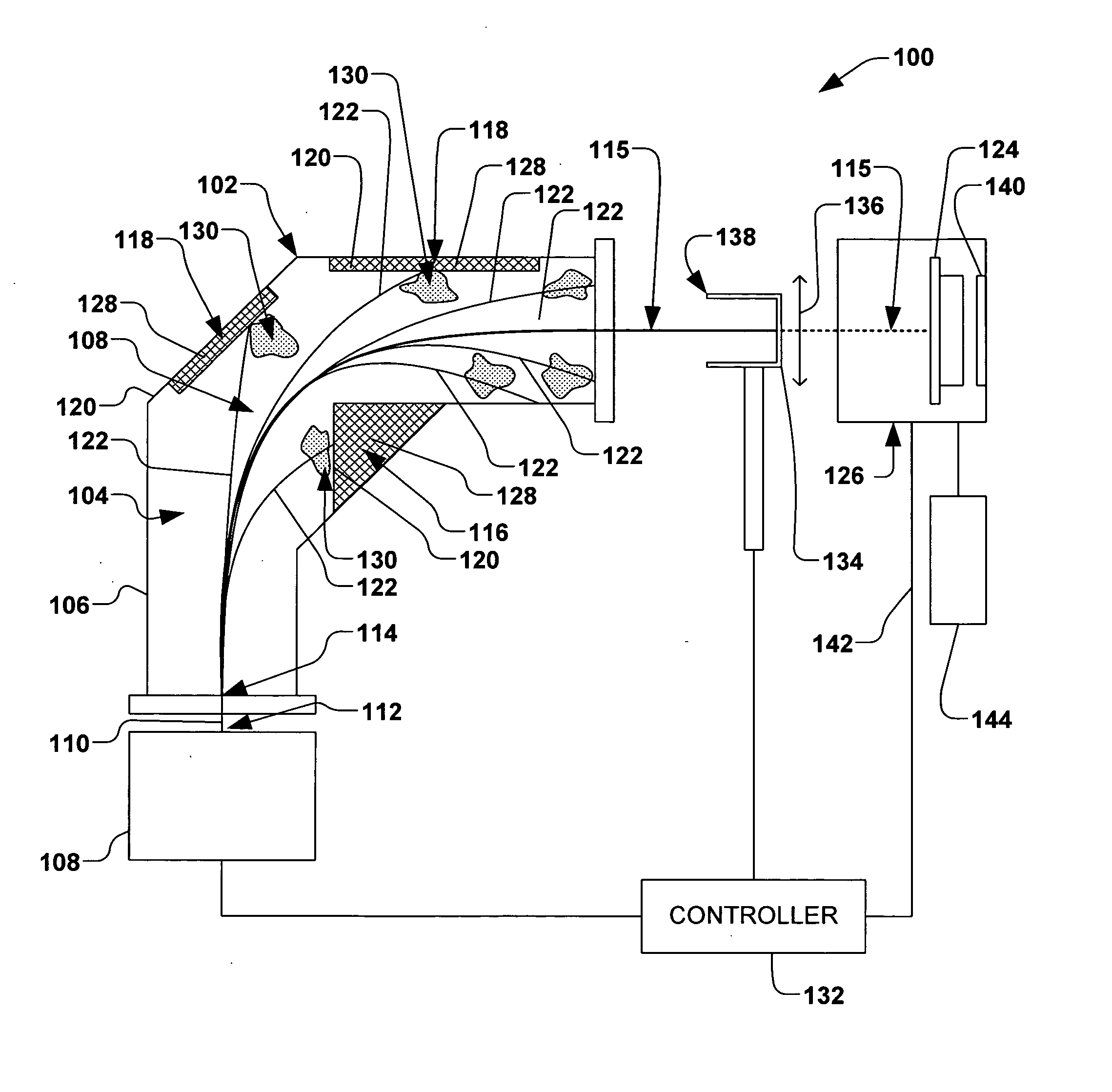
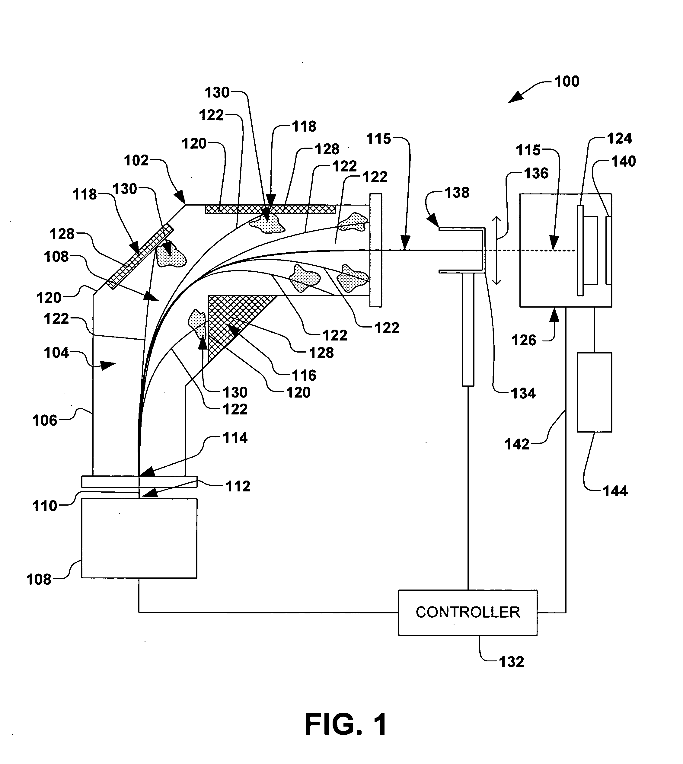
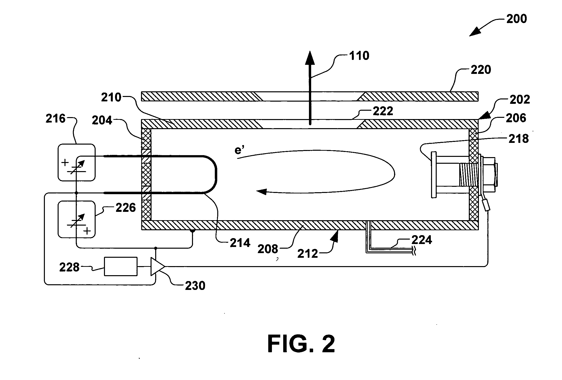
[0010] The present invention is directed generally toward a system and method for mitigating particulate contamination of a workpiece in an ion implantation system, wherein a control is provided for rapidly modulating an output of an ion source. The invention provides for more efficient duty cycles of the ion implantation system, while reducing contamination associated with conventional ion implantation systems. Rapid control of the ion source is provided by electrically controlling electron flux within an ion source chamber, rather than by relying on thermal control of the ion chamber filament or changes in arc voltage.
[0012] According to another aspect of the present invention, the ion source comprises an ion chamber, a filament-cathode, a mirror electrode, and a grid operable to vary the grid's potential relative to the filament. Accordingly, the grid is operable to control the number of the electrons available in the ion chamber for ionization. In accordance with another exemplary aspect of the invention, the current of the ion beam can be modulated between the minimal current and the implantation current in less than 20 microseconds, wherein the ion beam power is operable to be cleanly and efficiently ramped up or down in a selectable manner, thus mitigating contamination associated with maintaining the ion beam current at the implantation power during workpiece transfers, as well as mitigating the deleterious effects of relying on thermal control of the ion chamber filament or changes in arc voltage to modulate intensity of the ion beam.

Problems solved by technology

Operation of a typical ion implanter or other ion beam equipment (e.g., a linear accelerator), however, may result in the production of contaminant particles.
Consequently, particles entrained in an ion beam may be transported with the beam toward the workpiece, thus resulting in undesired contamination at the wafer.

Method used


Image

  • Particulate prevention in ion implantation
  • Particulate prevention in ion implantation
  • Particulate prevention in ion implantation

Examples


Embodiment Construction

[0018] The present invention is directed generally towards systems, apparatuses, and methods for generally preventing particulate contamination of a workpiece being subjected to an ion beam. Accordingly, the present invention will now be described with reference to the drawings, wherein like reference numerals may be used to refer to like elements throughout. It should be understood that the description of these aspects are merely illustrative and that they should not be interpreted in a limiting sense. In the following description, for purposes of explanation, numerous specific details are set forth in order to provide a thorough understanding of the present invention. It will be evident to one skilled in the art, however, that the present invention may be practiced without these specific details.

[0019] Typically, ion implantation systems run continuously; that is, an ion beam is formed within the ion implantation system, regardless of whether a workpiece is in place for implantat...


PUM

PropertyMeasurementUnit
Fractionaaaaaaaaaa
Fractionaaaaaaaaaa
Timeaaaaaaaaaa

Abstract

A system and method for mitigating contamination in an ion implantation system is provided. The system comprises an ion source, a power supply operable to supply power to a filament and mirror electrode of the ion source, a workpiece handling system, and a controller, wherein the ion source is selectively tunable via the controller to provide rapid control of a formation of an ion beam. The controller is operable to selectively rapidly control power to the ion source, therein modulating a power of the ion beam between an implantation power and a minimal power in less than approximately 20 microseconds based, at least in part, to a signal associated with a workpiece position. Control of the ion source therefore mitigates particle contamination in the ion implantation system by minimizing an amount of time at which the ion beam is at the implantation current.

Description

REFERENCE TO RELATED APPLICATION [0001] This application claims priority to and the benefit of U.S. Provisional Application Ser. No. 60 / 687,514 which was filed Jun. 3, 2005, entitled PARTICULATE PREVENTION IN ION IMPLANTATION, the entirety of which is hereby incorporated by reference as if fully set forth herein.FIELD OF THE INVENTION [0002] The present invention relates generally to an ion implantation system and method for implanting ions into a workpiece, and more specifically to a system and method for mitigating particulate contamination within an ion beam at various positions upstream of the workpiece. BACKGROUND OF THE INVENTION [0003] In the manufacture of semiconductor devices, ion implantation systems are employed to dope a semiconductor wafer or other workpiece with impurities. In such systems, an ion source ionizes a desired dopant element, which is extracted from the source in the form of an ion beam. The ion beam is typically mass analyzed to select ions of a desired c...

Claims


Application Information

Patent Timeline
IPC IPC(8): H01J37/08
CPCH01J37/045H01J37/09H01J37/244H01J37/302H01J2237/31705H01J2237/022H01J2237/026H01J2237/028H01J2237/30433H01J37/3171H01J37/08H01J37/304H01J37/317
Inventor BERRIAN, DONALD W.VANDERPOT, JOHN W.
Owner AXCELIS TECHNOLOGIES
Learn More