Sound-electricity conversion device, array-type ultrasonic transducer, and ultrasonic diagnostic apparatus

a conversion device and ultrasonic technology, applied in ultrasonic/sonic/infrasonic diagnostics, mechanical vibration separation, applications, etc., can solve the problems of preventing the sensitivity of a receiving transducer, excessive current flow or discharging phenomenon between the electrodes, and low electromechanical conversion efficiency of the crystal, so as to reduce the noise level of the ultrasonic diagnostic apparatus and stabilize the sound-electricity conversion characteristics.

Inactive Publication Date: 2006-12-21
HITACHI LTD
View PDF1 Cites 5 Cited by
  • Summary
  • Abstract
  • Description
  • Claims
  • Application Information

AI Technical Summary

Benefits of technology

[0026] Thus, the present invention stabilizes the sound-electricity conversion characteristics of the sound-electricity conversion device provided with the electrode short-circuit prevention film, and decreases the noise level of the ultrasonic diagnostic apparatus configured using the sound-electricity conversion device.

Problems solved by technology

In the Early Twentieth Century, experiments started for transmitting / receiving ultrasonic sound by using piezoelectric effect of quartz crystal, when a problem arose in that a crystal has low electromechanical conversion efficiency.
This prevented obtaining a sufficient sensitivity for, in particular, a receiving transducer and thus achieving its application to a practical product.
However, the Rochelle salt had a problem in crystal stability such as being very deliquescent, requiring a special attention to obtain stable piezoelectric characteristics.
However, in practice, when the electrode on the diaphragm side contacts or come close to contacting the silicon substrate, a short-circuit occurs causing an excessive current flow or discharging phenomenon between the electrodes.
In this occurrence, the excessive current, for example, may destroy the sound-electricity conversion device itself or the peripheral circuit system connected to the device.
However, the silicon nitride film formed by CVD includes more coupling deficiencies than, for example, a silicon oxide film formed by thermal oxidation, and therefore is characteristically subject to electrification when applied with a high voltage.
In addition, the amount of electric charge electrified drifts depending on the applied voltage value and with the passage of time, and does not stabilize.
Therefore, even if the same voltage is applied between the electrodes or if the diaphragm electrodes are displaced by the same amount, the amount of electric charge induced in the electrodes would change and drift.
This causes the sound-electricity conversion characteristics of the sound-electricity conversion device to drift and become unstable.
This is because when the sound-electricity conversion characteristics of each of the devices constructing the array-type ultrasonic transducer drift independently, the entirety of an ultrasonic diagnostic apparatus using the array-type ultrasonic transducer experiences a considerable increase in the sound noise level when forming transmission and reception beams.
As discussed above, the ultrasonic transducer using the semiconductor diaphragm type sound-electricity conversion device has not sufficiently solved the problems of sensitivity and stability.

Method used


Image

  • Sound-electricity conversion device, array-type ultrasonic transducer, and ultrasonic diagnostic apparatus
  • Sound-electricity conversion device, array-type ultrasonic transducer, and ultrasonic diagnostic apparatus
  • Sound-electricity conversion device, array-type ultrasonic transducer, and ultrasonic diagnostic apparatus

Examples


Embodiment Construction

[0035] Referring to the drawings, an embodiment of the present invention will be described in detail below.

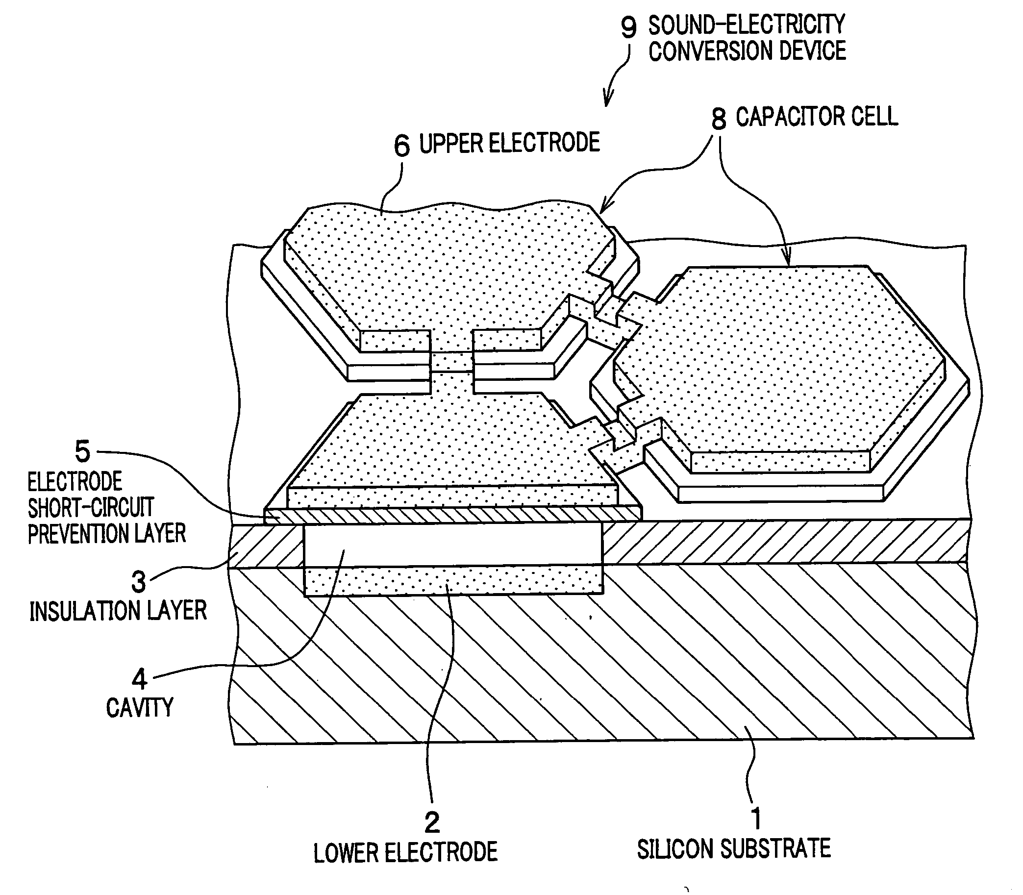
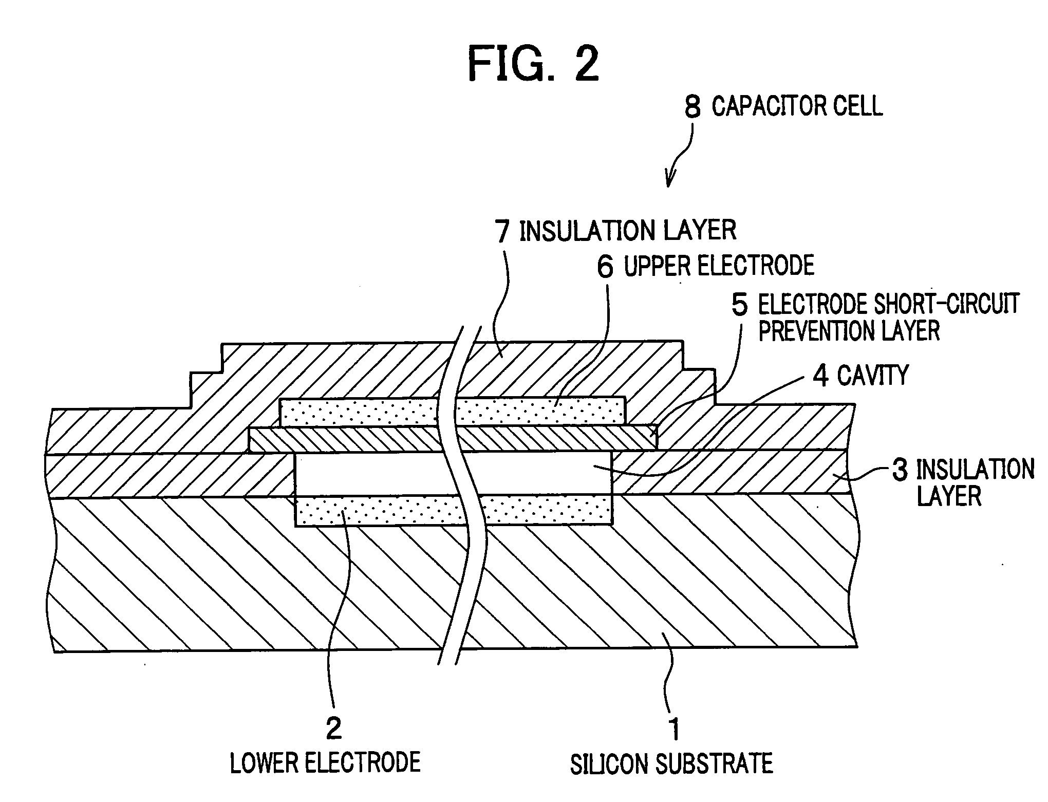
[0036]FIG. 1 is a drawing to show a structural concept of a semiconductor diaphragm type sound-electricity conversion device according to an embodiment of the present invention. FIG. 2 is a drawing to show a sectional structure of a capacitor cell as a unitary constructional element of the sound-electricity conversion device.

[0037] As shown in FIG. 1, the sound-electricity conversion device 9 is configured with a plurality of capacitor cells 8 that are two-dimensionally arranged in a honeycomb shape on a silicon substrate 1. Each of the capacitor cells 8 is a capacitor comprising a lower electrode 2 formed on the silicon substrate 1 and an upper electrode 6 formed opposite to the lower electrode 2, the upper and lower electrodes sandwiching a cavity 4.

[0038] The upper electrode 6 flexes toward the lower electrode 2 when applied with a pressure, i.e., sound pressure, from the...


PUM


Abstract

The present invention aims to stabilize sound-electricity conversion characteristics of a diaphragm-type sound-electricity conversion device as well as to decrease the noise level of an ultrasonic diagnostic apparatus using the sound-electricity conversion device. The sound-electricity conversion device is configured by a capacitor cell including a lower electrode formed on a silicon substrate and an upper electrode over the lower electrode, the lower and upper electrodes sandwiching a cavity. An electrode short-circuit prevention film is formed on the upper electrode on the cavity side. The electrode short-circuit prevention film is formed of a material with an electrical time constant shorter than 1 second and longer than 10 microseconds, such as silicon nitride containing a stoichiometrically excessive amount of silicon. As a result, the electrode short-circuit prevention film has small electric conductivity, and thus it is made possible to prevent the film from being charged with electric charge and to avoid the drift of the electric charge. Consequently, the sound-electricity conversion characteristics of the sound-electricity conversion device stabilize, and further the sound noise level of the ultrasonic diagnostic apparatus decreases.

Description

CLAIM OF PRIORITY [0001] The present application claims priority from Japanese application JP2005-179959 filed on Jun. 20, 2005, the content of which is hereby incorporated by reference into this application. BACKGROUND OF THE INVENTION [0002] 1. Field of the Invention [0003] The present invention relates to a diaphragm-type sound-electricity conversion device produced by using a semiconductor microfabrication technique, and an array-type ultrasonic transducer and an ultrasonic diagnostic apparatus using the sound-electricity conversion device. [0004] 2. Description of the Related Art [0005] In the Early Twentieth Century, experiments started for transmitting / receiving ultrasonic sound by using piezoelectric effect of quartz crystal, when a problem arose in that a crystal has low electromechanical conversion efficiency. This prevented obtaining a sufficient sensitivity for, in particular, a receiving transducer and thus achieving its application to a practical product. Then, Rochell...

Claims


Application Information

Patent Timeline
Patent Type & Authority Applications(United States)
IPC IPC(8): H01L41/00A61B8/00H04R19/00
CPCB06B1/0292
Inventor UMEMURA, SHINICHIROAZUMA, TAKASHINAGATA, TATSUYAFUKUDA, HIROSHIMINE, TOSHIYUKIMACHIDA, SYUNTARO
Owner HITACHI LTD
Why Eureka
Try Eureka