Process control system, process control method, and method of manufacturing electronic apparatus

a technology of process control system and process control method, which is applied in the direction of program control, total factory control, instruments, etc., can solve the problems of reducing the process capability of manufacturing trench capacitors, difficult to control the manufacturing process in accordance with the miniaturization, and inability to control the recess depth with high accuracy

Active Publication Date: 2006-12-21
KIOXIA CORP
View PDF2 Cites 15 Cited by
  • Summary
  • Abstract
  • Description
  • Claims
  • Application Information

AI Technical Summary

Benefits of technology

[0067]FIG. 15 is a diagram showing an exemplary configuration of a process control system according to a second embodiment of the present invention;
[0068]FIG. 16 is a graph showing an example of a correlation between an apparatus parameter and a feature quantity for use in a process control method according to the second embodiment of the present invention;
[0069]FIG. 17 is a flowchart showing an example of the process control method according to the second embodiment of the present invention;

Problems solved by technology

For example, in semiconductor apparatuses such as large-scale integrated circuits (LSIs), which are formed of multi-layered micropatterns, it has been made difficult to control the manufacturing process in accordance with the miniaturization thereof.
For this reason, even if an etching time for an a-Si film embedded in a deep trench is controlled on the basis of an end-point detection time, a recess depth cannot be controlled with high accuracy.
As a result, the process c

Method used


Image

  • Process control system, process control method, and method of manufacturing electronic apparatus
  • Process control system, process control method, and method of manufacturing electronic apparatus
  • Process control system, process control method, and method of manufacturing electronic apparatus

Examples


first embodiment

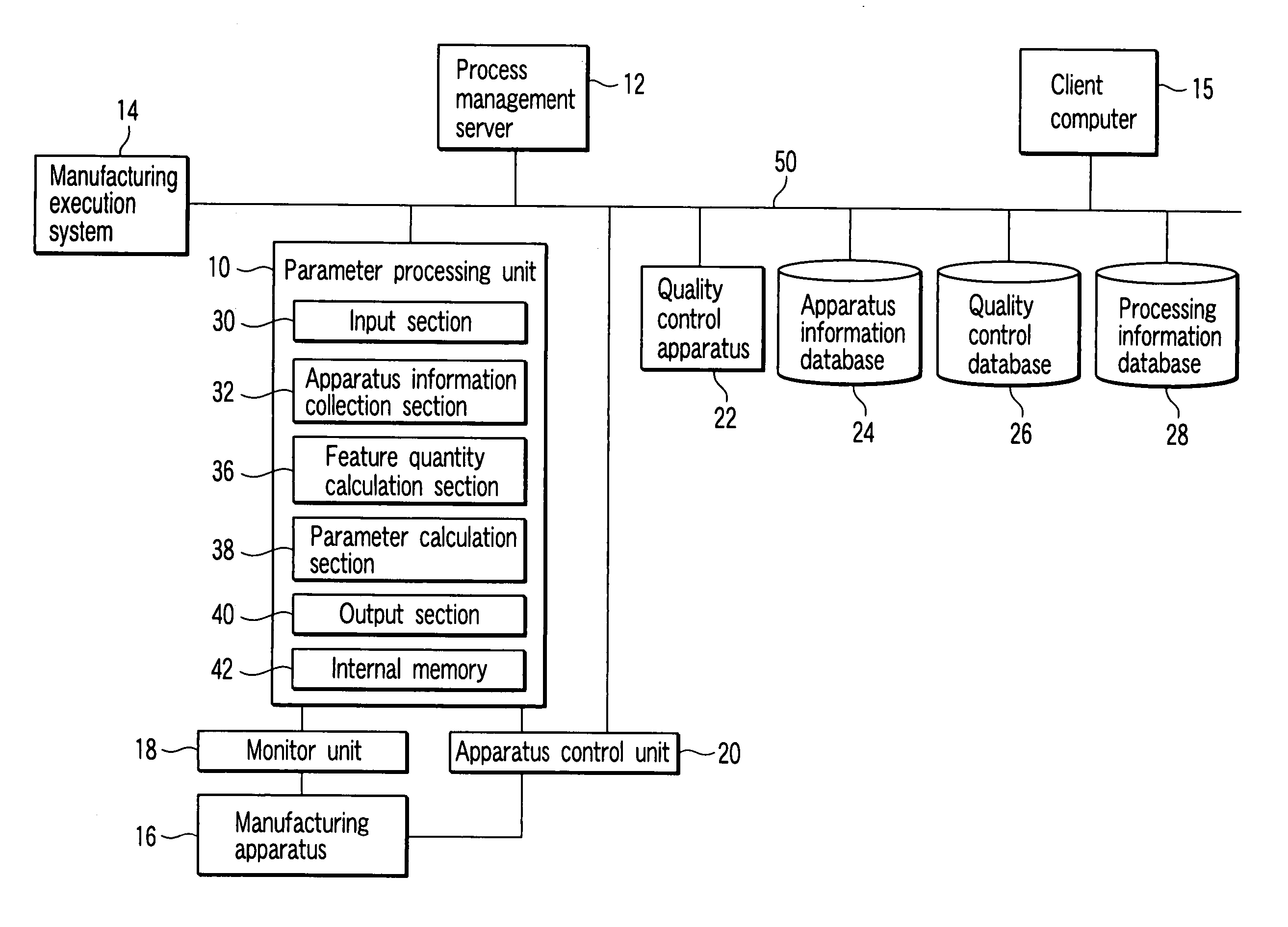
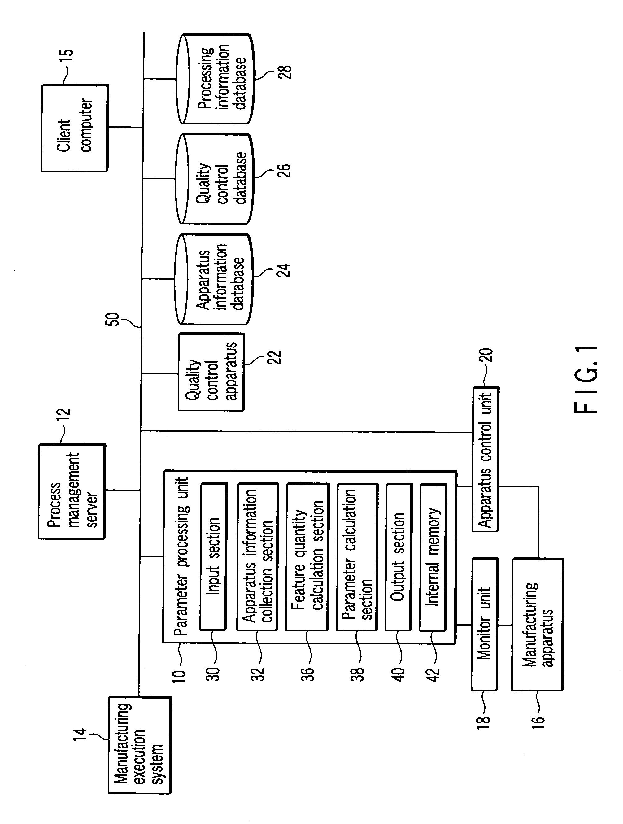
[0074] A process control system according to a first embodiment of the present invention comprises, as shown in FIG. 1, a parameter processing unit 10, a process management server 12, a manufacturing execution system 14, a client computer 15, a manufacturing apparatus 16, a monitor unit 18, an apparatus control unit 20, a quality control apparatus 22, an apparatus information database 24, a quality control database 26, and a processing information database 28, etc. Further, the parameter processing unit 10 includes an input section 30, an apparatus information collection section 32, a determination section 34, a feature quantity calculation section 36, a parameter calculation section 38, an output section 40, an internal memory 42, etc.

[0075] The parameter processing unit 10, the process management server 12, the manufacturing execution system 14, the client computer 15, the apparatus control unit 20, the quality control apparatus 22, the apparatus information database 24, the qual...

modified example

[0099] In a process control method according to a modified example of the first embodiment of the invention, descriptions will be given by using a manufacturing process for a semiconductor device under the 0.13 μm design rule, for example, a DRAM mixed loading logic product as an example. For ease of explanation, as an example of a manufacturing process to be controlled, there will be described a recess RIE process in which a part of an a-Si film embedded in a deep trench at a DRAM portion is removed to an arbitrary depth, with reference to the process flowchart of FIG. 11 and process cross-sectional views of FIG. 12 to FIG. 14.

[0100] (a) An oxide film 76 is formed on the surface of a substrate (wafer) 60 by a thermal oxidation process in step S180. A nitride film 77 is deposited on the oxide film 76 by an Si3N4CVD process in step S181.

[0101] (b) A mask pattern such as photo resist is formed on the nitride film 77 in a photolithography process in step S182. In a deep trench RIE pr...

second embodiment

[0112] A process control system according to a second embodiment of the present invention comprises, as shown in FIG. 15, an apparatus information collection unit 13, a correlation preparation unit 11, a process management unit 17, a manufacturing execution system 14, a manufacturing apparatus 16, a monitor unit 18, an apparatus control unit 20, a quality control apparatus 22, an apparatus information database 24, a quality control database 26, a control information database 28, and the like. Further, the process management unit 17 includes an input section 30, a determination section 32, a feature quantity calculation section 34, a target value calculation section 36, a parameter calculation section 38, an output section 40, and an internal memory 42.

[0113] The apparatus information collection unit 13, the correlation preparation unit 11, the process management unit 17, the manufacturing execution system 14, the apparatus control unit 20, the quality control apparatus 22, the appa...


PUM


Abstract

A process control system includes a client computer which prepares a correlation between a reference monitored value of apparatus information and a feature quantity, a manufacturing execution system which prepares a processing recipe describing, as a first setting value in an actual manufacturing process, a value of the control parameter, an apparatus information collection section which collects an objective monitored value of the apparatus information in operation of the actual manufacturing process with the first setting value, a feature quantity calculation section which calculates a value of a feature quantity corresponding to the objective monitored value based on the correlation, a parameter calculation section which calculates a second setting value in the actual manufacturing process on the basis of the value of the feature quantity, and an apparatus control unit which changes the processing recipe with the second setting value being as a setting value of the second step.

Description

CROSS-REFERENCE TO RELATED APPLICATIONS [0001] This application is based upon and claims the benefit of priority from prior Japanese Patent Applications No. 2005-180659, filed Jun. 21, 2005; and No. 2005-272019, filed Sep. 20, 2005, the entire contents of both of which are incorporated herein by reference. BACKGROUND OF THE INVENTION [0002] 1. Field of the Invention [0003] The present invention relates to a process of manufacturing an electronic apparatus, and in particular, to a process control system which controls a manufacturing process, a process control method, and a method of manufacturing an electronic apparatus. [0004] 2. Description of the Related Art [0005] In order to realize high-performance electronic apparatuses, a manufacturing process with high accuracy, uniformity, and reproducibility is required. In electronic apparatuses such as semiconductor integrated circuits (ICs) and liquid crystal displays (LCDs), miniaturization and multilayer manufacturing have progressed...

Claims


Application Information

Patent Timeline
IPC IPC(8): G06F19/00
CPCG05B19/41875G05B2219/31477G05B2219/45031G05B2219/32097G05B2219/32057Y02P90/02
Inventor SUGAMOTO, JUNJIUSHIKU, YUKIHIROAKIYAMA, KAZUTAKAHARAKAWA, SHOICHI
Owner KIOXIA CORP
Why Eureka
Try Eureka