Apparatus and method for detection of vacuum ultraviolet radiation

Active Publication Date: 2006-12-28
THERMO FISHER SCIENTIFIC INC
View PDF10 Cites 5 Cited by
  • Summary
  • Abstract
  • Description
  • Claims
  • Application Information

AI Technical Summary

Benefits of technology

[0019] A dry pump has two primary advantages over the Polyvac® system in particular. Firstly, it does not require oil and so the problem of backstreaming is addressed. Secondly, it is relatively less costly than a rotary vane pump or turbomolecular pump.
[0021] The inventors have found, surprisingly, that by addition of a substantially UV transparent gas to the chamber, absorption of UV radiation below about 200 nm by the residual atmospheric gases (which the dry pump is unable to extract) is significantly reduced, such that the system operates successfully even with a dry pump.
[0025] A much lower (at least 5-6 times lower) flow rate of UV transparent gas is employed in the present invention, coupled with a pump to evacuate the chamber (the above-mentioned prior art tends to operate at or around atmospheric pressure). In a preferred embodiment, the pump may be a dry pump or the like which further reduces the cost over and above the annual running cost reduction through a decrease in consumables. Whilst the flow rate of UV transparent gas is, in the present invention, somewhat higher than that of the Polyvac® system described above, it will be noted that the gas flow in the Polyvac® system is not intended to operate in combination with a vacuum so as to prevent absorption but is instead essentially to prevent backstreaming of pump oil vapour.
[0030] Whilst the two aspects of the present invention both provide vacuum ultraviolet radiation detection apparatus with cheaper component consumables than the prior art, it will nevertheless be understood that the twin solutions are by no means mutually exclusive and that an apparatus having both a dry pump and a relatively low flow rate of UV transparent gas will provide particular advantages.

Problems solved by technology

Nevertheless, currently available dry pumps are only able to produce a relatively poor vacuum.
As a result, dry pumps (at least without further assistance) have previously been considered unusable in VUV spectral analysis.

Method used


Image

  • Apparatus and method for detection of vacuum ultraviolet radiation
  • Apparatus and method for detection of vacuum ultraviolet radiation
  • Apparatus and method for detection of vacuum ultraviolet radiation

Examples


Embodiment Construction

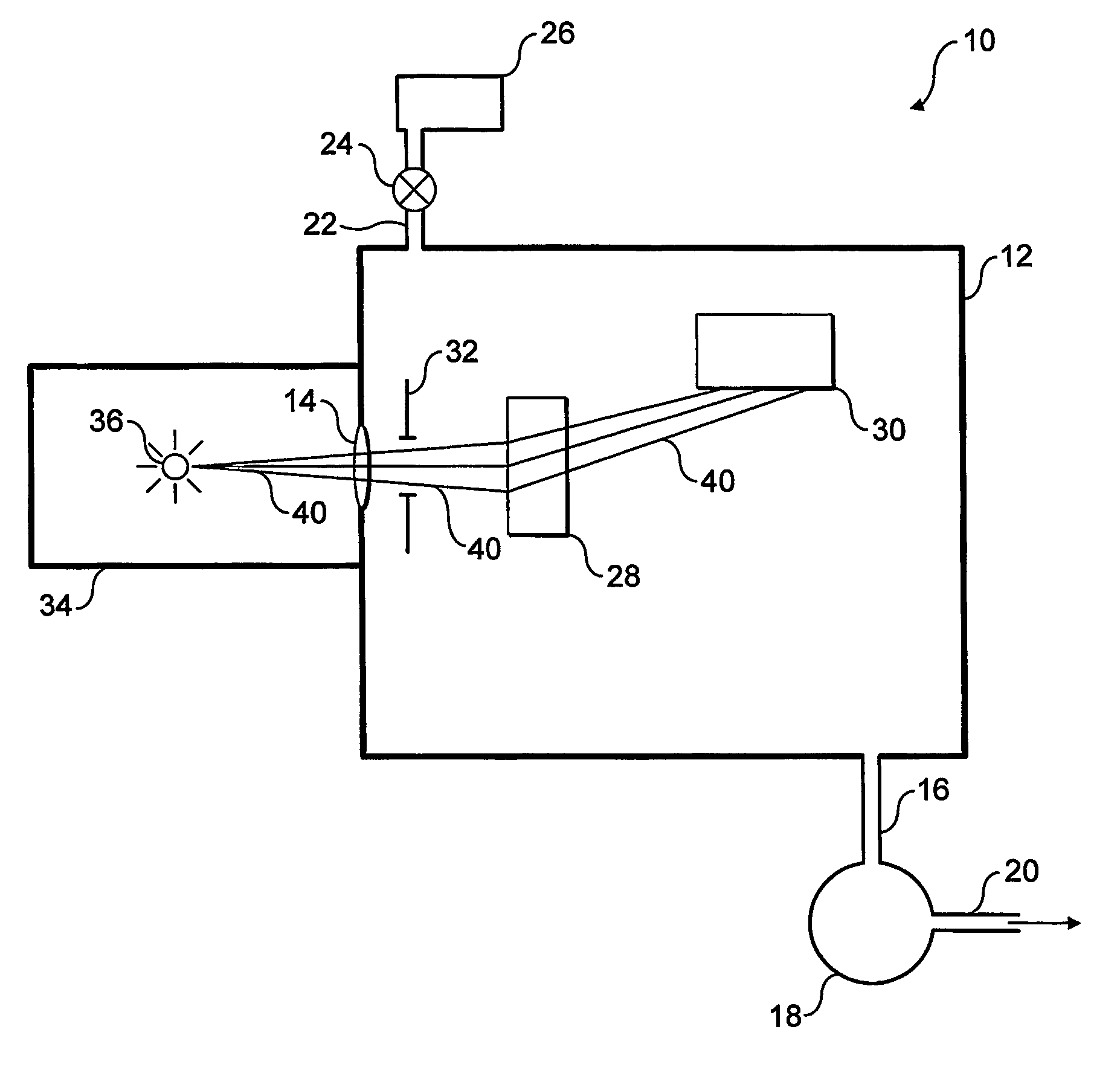
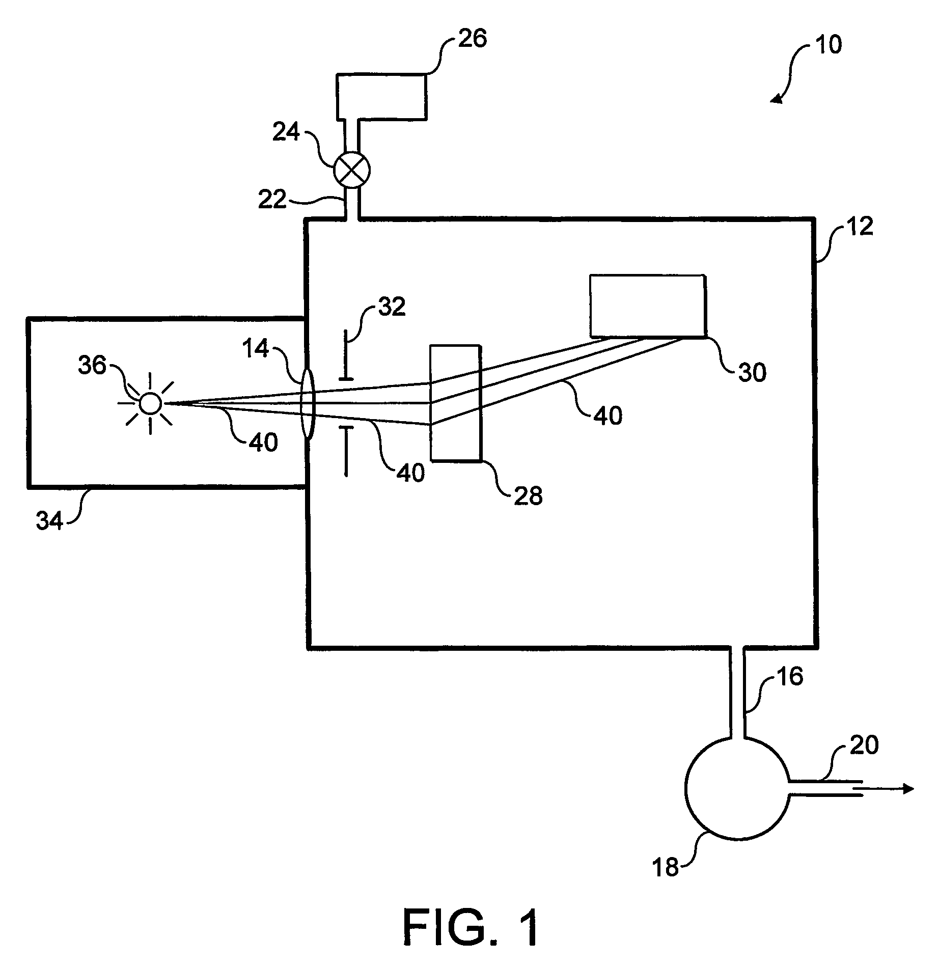
[0035] Referring to FIG. 1, apparatus 10 embodying the present invention is shown in highly schematic form. The apparatus comprises a spectrometer housing or chamber 12 with a window 14 on one wall of the housing. The housing comprises an outlet port 16 and a vacuum pump 18 which is arranged to evacuate the housing to low vacuum pressures only. By low vacuum pressure it is meant a vacuum pressure of between atmosphere and 100 Pa (1 mbar). The vacuum pump vents directly to atmosphere via a pump outlet 20.

[0036] The housing 12 also comprises an inlet port 22. The inlet port is connected via a valve 24, to a gas supply 26. The gas supply contains a UV transparent gas, such as argon or nitrogen. The valve 24 might be of a solenoid or needle type or a mass flow controller. Other devices allowing an appropriate flow adjustment might be used.

[0037] A grating 28, or appropriate diffracting / refracting means, is disposed within the housing 12 such that radiation passing through the window 1...


PUM


Abstract

Vacuum ultraviolet radiation detection apparatus (10) comprises a radiation detector (30) in a chamber (12). The detector (30) receives ultraviolet radiation from a radiation source (36). The chamber is evacuated using a dry vacuum pump (18) to a relatively poor vacuum of no less than 5 Pa. UV transparent gas is supplied from a gas supply (26), into the chamber (12) at a relatively low flow rate (around 0.1 litres / minute) so as to provide an overall pressure in the chamber (12) of between 100 and 1,000 Pa. The use of a relatively inexpensive pump coupled with a lower gas flow rate provides significant cost savings.

Description

TECHNICAL FIELD OF THE INVENTION [0001] This invention relates to ultraviolet spectroscopy. In particular, but not exclusively, this invention relates to detecting vacuum ultraviolet (VUV) radiation and atomic emission spectra in the VUV region of the electromagnetic spectrum. BACKGROUND TO THE INVENTION [0002] Ultraviolet (UV) radiation is electromagnetic radiation lying between the visible and X-ray regions of the spectrum, that is between 380 nm and 5 nm. Vacuum ultraviolet (VUV) radiation is part of the UV region of the spectrum in which radiation is absorbed by air. As a result, any experiments arranged to detect this VUV radiation are usually performed in a vacuum. The wavelength of VUV radiation is less than 200 nm. [0003] Atomic emission spectroscopy is a well known technique used to determine constituent molecules or atoms of a sample. When atoms excited to a high energy state relax to a lower energy state, or to the ground energy state, photons are emitted. The wavelength ...

Claims


Application Information

Patent Timeline
IPC IPC(8): G01J1/42G01J3/443
CPCG01J3/443G01J1/429
Inventor VINCENT, FRANCOISCABRAS, ANTONIO
Owner THERMO FISHER SCIENTIFIC INC
Why Eureka
Try Eureka