Integrated hydrogen production and processing system and method of operation

a hydrogen production and processing system technology, applied in the direction of manufacturing tools, instruments, electric circuits, etc., can solve the problems of long periods of inefficient operation of the electrolyzer at lower temperatures, loss of system overall efficiency, and reducing system overall efficiency, so as to achieve the effect of increasing the temperature of the electroly

Inactive Publication Date: 2007-01-04
GENERAL ELECTRIC CO
View PDF7 Cites 53 Cited by
  • Summary
  • Abstract
  • Description
  • Claims
  • Application Information

AI Technical Summary

Benefits of technology

[0006] Briefly, according to one embodiment a method of operating an integrated hydrogen production and processing system is provided. The method includes operating an electrolyzer to produce hydrogen from water and utilizing heat generated from the electrolyzer to increase a temperature of an electrolyte in a fi

Problems solved by technology

In initiation of operation of certain conventional electrolyzers, relatively long time delays are encountered for the electrolyte to reach the desired operating temperature, thereby resulting in long periods of inefficient operation of the electrolyzer at lower temperatures.
However, adding an external h

Method used


Image

  • Integrated hydrogen production and processing system and method of operation
  • Integrated hydrogen production and processing system and method of operation
  • Integrated hydrogen production and processing system and method of operation

Examples


example 1

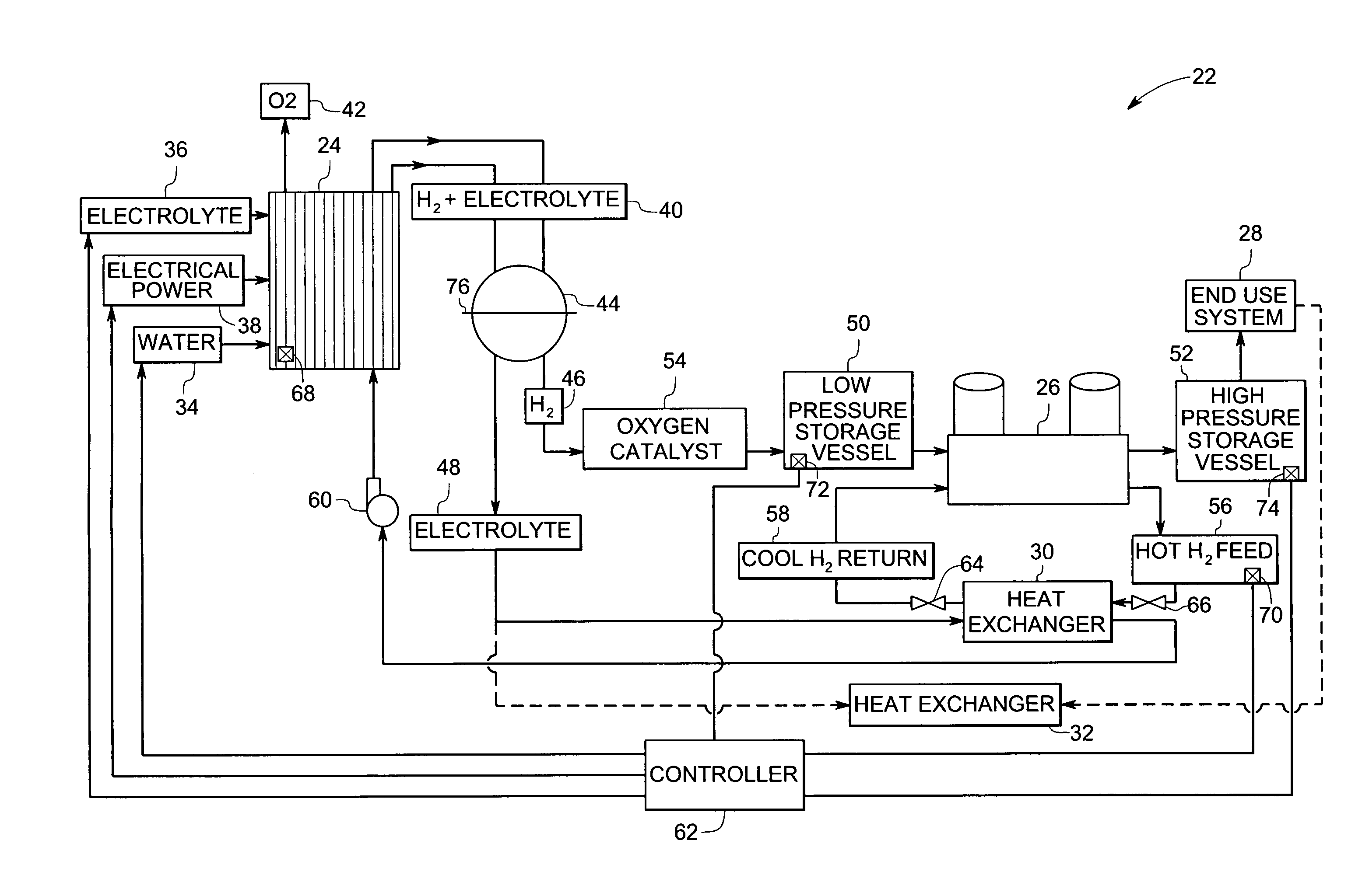
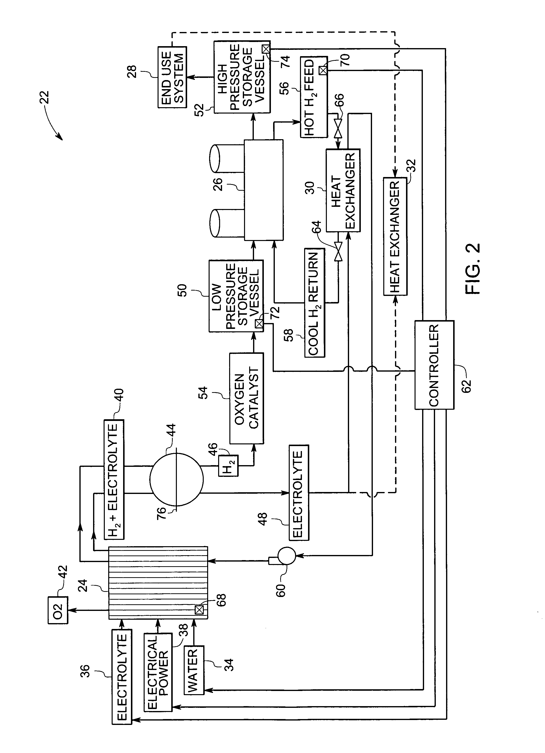
[0032] In an exemplary 250 kW integrated hydrogen production and processing system hydrogen is produced at the rate of 5 kg / hr. The system operates for 16 hours a day with about 8 hours of downtime to produce 80 kg of hydrogen per day. During the downtime, the electrolyzer is switched off. As a result, the electrolyte temperature decreases at a rate dependent on multiple factors such as exposed surface area, pipe thickness and insulation. In this exemplary embodiment, assumptions were made for stack and system geometries.

[0033] In the integrated hydrogen production and processing system hydrogen generated by the electrolyzer is stored in a low pressure storage vessel. Further, a portion of the hydrogen is purified, compressed and stored in a high pressure storage vessel. As a result, the temperature of the hydrogen increases and is required to be cooled for storage in the high pressure storage vessel. Thus, for 80 kg of hydrogen produced in one day approximately 880 MJ of heat must...

example 2

[0035] In the exemplary hydrogen production and processing system of Example 1, the electrolyzer temperature is maintained during 8 hours of downtime by extracting heat from an end use system. Again, the electrolyte cools at a rate of about 6 MJ / hr based on convective and radiative cooling assumptions as discussed above. This corresponds to about 5 degree temperature drop per hour. Assuming that the hydrogen engine is about 40% efficient, approximately 60% of the energy consumed to operate the engine is available as waste heat. The 200 kW engine in this example rejects heat at a rate of about 58 MJ / hr assuming losses in the heat exchanger. As can be seen, the available heat from the engine exceeds the energy needed to maintain the operating temperature of the electrolyte. Therefore, by coupling the heat from the engine to a heat exchanger the electrolyte temperature can be maintained at a required operating temperature continuously during the downtime. Advantageously, the ability to...


PUM

PropertyMeasurementUnit
Temperatureaaaaaaaaaa
Pressureaaaaaaaaaa
Flow rateaaaaaaaaaa

Abstract

A method of operating an integrated hydrogen production and processing system is provided. The method includes operating an electrolyzer to produce hydrogen from water and utilizing heat generated from the electrolyzer to increase a temperature of an electrolyte in a first mode of operation. The method also includes heating the electrolyte in a second mode of operation by extracting heat from a hydrogen compressor to increase or maintain the temperature of the electrolyte during periods when electrolysis is not performed in the electrolyzer or during startup of the electrolyzer.

Description

BACKGROUND [0001] The invention relates generally to hydrogen production and processing systems, and more particularly, to enhancement of performance of an integrated hydrogen production and processing system, that may include, but is not limited to, hydrogen purification, compression, and storage sub-systems. [0002] Various types of hydrogen production systems have been designed and are in use. For example, electrolyzer systems generate hydrogen through electrolysis of water. The hydrogen acts as an energy carrier, and can be converted back to electricity for power generation or distributed for use as a fuel. Typically, hydrogen generated from such systems is purified and compressed for storage before it is consumed in an end use system. Many view future hydrogen applications in terms of energy production with hydrogen being produced through electrolysis for direct use in producing power. For example, the end use system may be of a business or industrial nature where the stored hyd...

Claims


Application Information

Patent Timeline
IPC IPC(8): C25B1/02
CPCC25B1/04Y02E60/366C25B15/02Y02E60/36
Inventor LIBBY, CARA SUZANNEBOURGEOIS, RICHARD SCOTT
Owner GENERAL ELECTRIC CO
Why Eureka
Try Eureka