[0027] In some cases, by using a single resistance element for saving the binary information, it is possible to reduce the circuitry outlay for the non-volatile
memory cell. For example, the use of a single resistance element may be used for the
layout of the memory
cell since a single resistance element, which may be arranged between two upper
metal layers, may be connected. In some cases, a small part of the
metal layers provided for the wiring is occupied thereby. Moreover, the use of a single resistance element reduces the number of circuit elements which serve for
programming and retrieving the saved information.
[0030] In one embodiment, the means for retrieving the binary information may include a means for initializing the potential of the second storage node with a fixed value, for example with the ground potential (VSS) or the positive
operating voltage potential (VDD). It is thereby possible to put the second storage node into a defined state prior to the actual retrieval of the binary information. This measure prevents the retrieval of the binary information from being influenced by the state of the second storage node prior to the retrieval. For the case where the resistance element is at
high resistance during the retrieval of the saved information, the potential of the second storage node is changed slightly by means of the resistance element during the retrieval. If the state of the second storage node is undefined, the change in potential, proceeding from an unfavorable potential value, is possibly too small to put the volatile memory element into the saved state. According to one embodiment of the invention, however, the state of the second storage node is initialized with a known fixed value, so that the volatile memory element toggles reliably into the correct state independently of the previous state of the second storage node. The robustness during the retrieval of the saved information is thus increased with the aid of this measure.
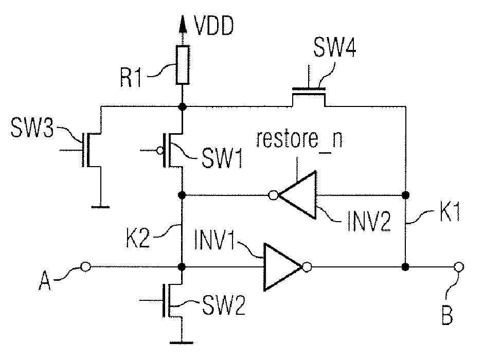
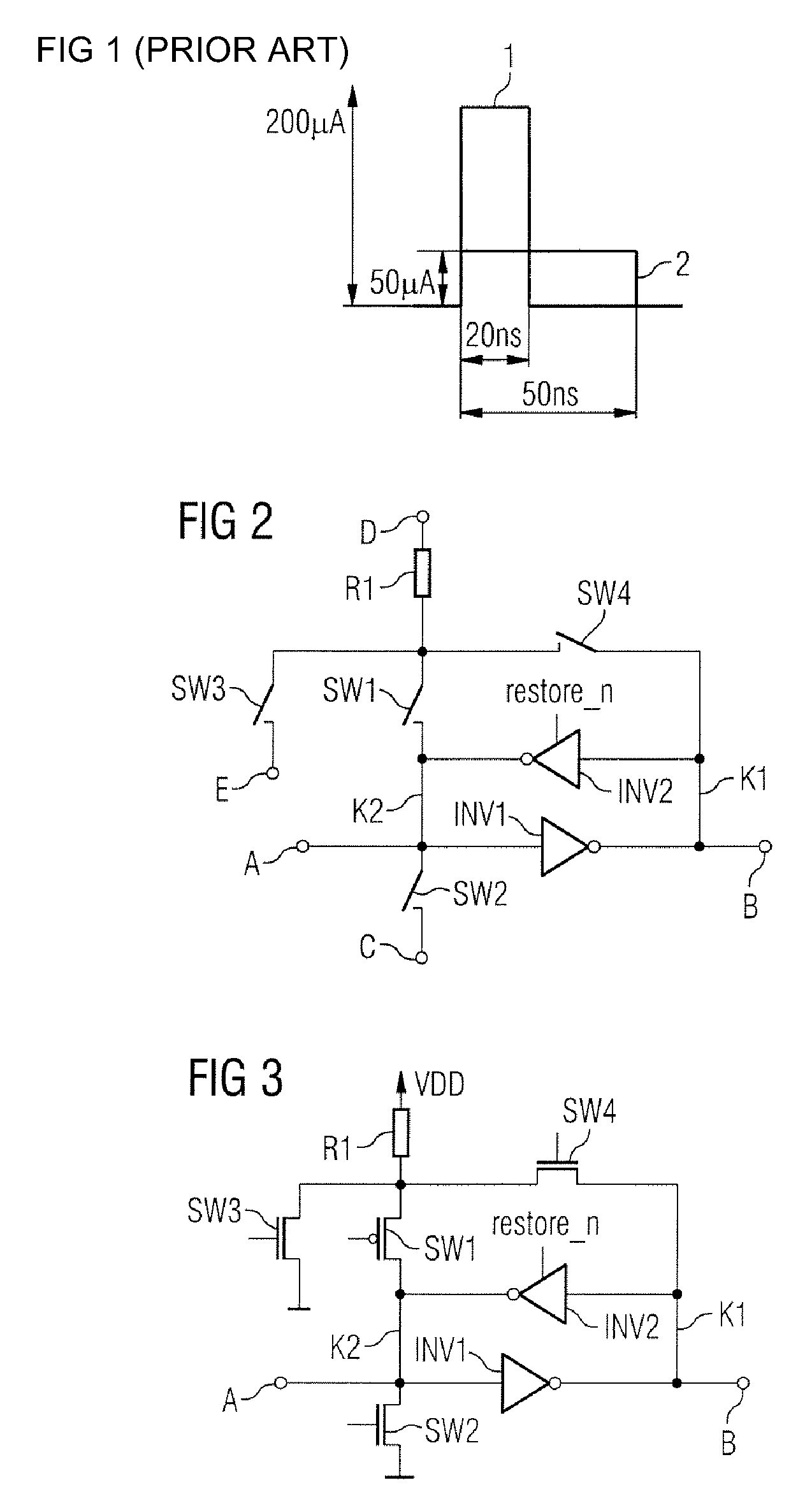
[0037] In one embodiment, two separate switches may be used for the first and the second switch. This results in an additional degree of freedom in the configuration of the non-volatile memory cell. Given suitable
dimensioning of the first and of the second switch, the currents can in each case be set optimally with regard to the save operation and the restore operation. This makes it possible to prevent, for example, a situation in which such a large current flows during the restore operation that the resistance element is reprogrammed (destructive read-out).
[0038] By means of a suitable choice of the
transistor type (N- or P-MOS) for implementing the first or respectively the second switch, it is furthermore also possible for the
voltage drop across the programmable resistance element to be chosen differently in the case of a closed first or respectively second switch. Thus, for example, in the case of an implementation with complementary transistors, it is possible to provide that the full
voltage swing is dropped across the programmable resistance element during the save operation, while the
voltage swing is reduced by the
threshold voltage of the turned-on
transistor during the restore operation. This makes it possible, on the one hand, to reduce the
power consumption and the thermal heating of the resistance element during the restore operation; on the other hand, it may thereby possible to provide, in the read case, that the voltage which reprograms the resistance element is not exceeded.
[0042] In an alternative embodiment, the fourth switch may be used directly for the retrieval of the saved information instead of for the initialization of the second storage node. If the second and fourth switches are closed, the resistance element, the closed second switch and the closed fourth switch act as a
voltage divider. In this case, the potential at the second storage node between the fourth and second switches is established in a manner dependent on the resistance value of the resistance element and thus, according to the saved binary information. If the saved binary information is retrieved by means of the
voltage divider, as described above, the temporal synchronization of the switch position of the second and fourth switches may be simplified. In this embodiment, the second and fourth switches can be controlled by means of the same
signal. In this case, in order to
restrict the
power loss consumption and in order to prevent a destructive read-out, the current in the
voltage divider may be limited. This may be provided by choosing the resistance Ron of the second switch with a sufficient magnitude in the case of the closed switch position.
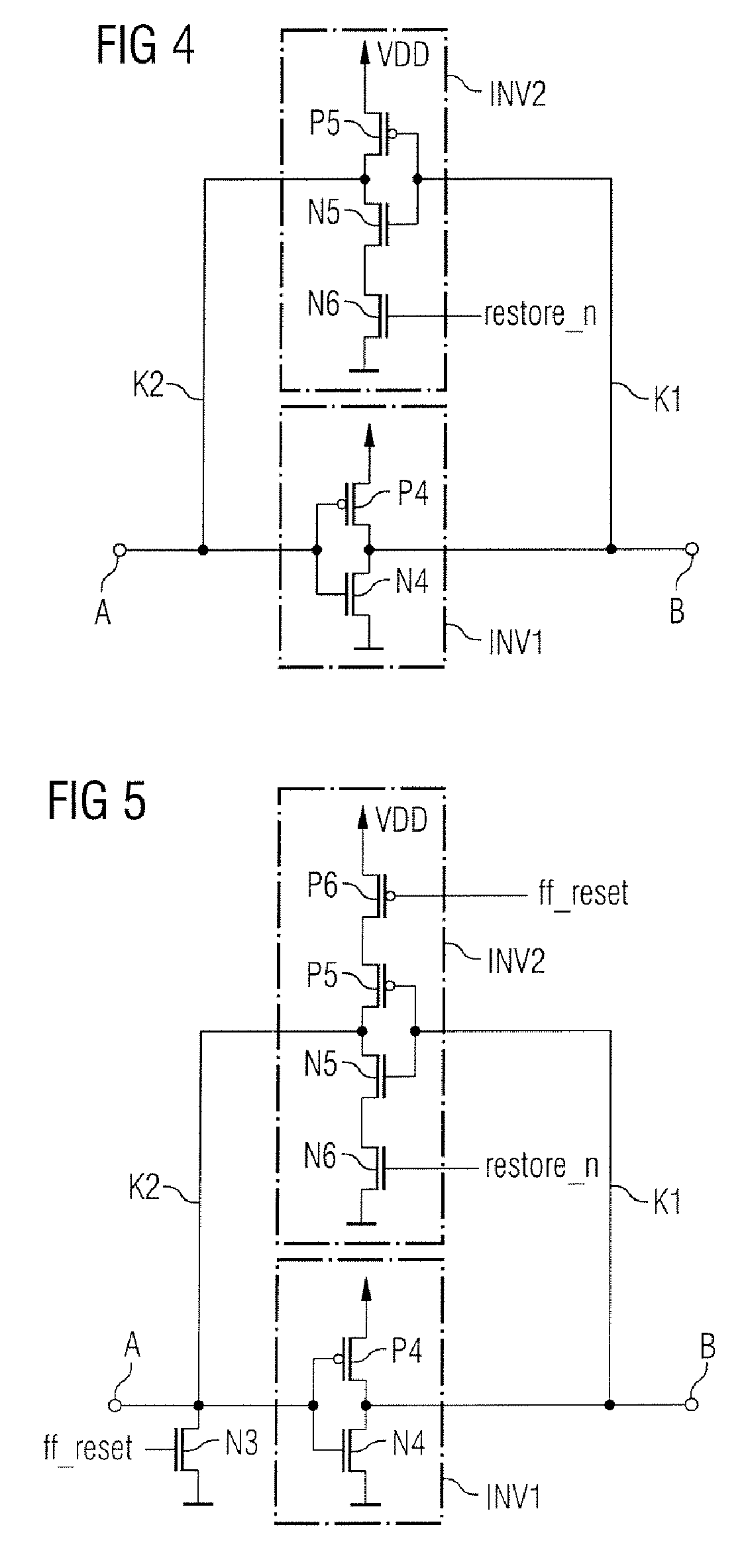
[0043] In one embodiment, the volatile memory means may be reset into a specific state, that is to say the volatile memory means may include a reset input. In this case, the fourth switch may be used for both initializing the second storage node and directly reading out the saved information and also for resetting the memory means. The fourth switch may be thus doubly utilized, so that the number of switches used may be reduced by one switch.

