External cavity laser diode system and method thereof

a laser diode and laser diode technology, applied in the direction of laser details, optical resonator shape and construction, semiconductor lasers, etc., can solve the problems of fewer than a hundred milliwatt to a watt of power, the temperature sensitivities of the device, and the conventional device does not address the problem of device turning on and off again, etc., and it has not been determined how well the emitter array can be locked over a 50 nm bandwidth using

Inactive Publication Date: 2007-01-04
COHERENT INC
View PDF24 Cites 59 Cited by
  • Summary
  • Abstract
  • Description
  • Claims
  • Application Information

AI Technical Summary

Benefits of technology

[0024] The coherent arrays, when operated in a narrow bandwidth mode, can be individually locked to reference wavelengths that are precisely spaced a fixed wavelength apart. These lasers or laser arrays can then be combined on a grating to produce a color combined beam that has the output power that is the sum of the two sources, but with the same spatial coherence as anyone of the sources used. This technique will enable scaling the output power of the laser system.

Problems solved by technology

However, most of the previous efforts resulted in only a few hundred milliwatts to Watts of power.
These issues include the high current that needs to be delivered to the surface emitter array, the heat load on the phase conversion plate used to improve the fill factor, and the long term stability of injection locking a source, which must start within the locking bandwidth of the master emitter.
While the above-mentioned conventional device may demonstrate long term phase locked stability, the conventional device does not address what happens when the device is turned on and off again, or the temperature sensitivities of the device.
However, it has not been determined how well the emitter arrays can be locked over a 50 nm bandwidth using this SBM technique.
Additionally, the SBM technique has not been extended to applications utilizing over 100,000 emitters.
However, these devices have a problem in scaling-up the devices.
In addition, as the diameter of the disc is expanded to handle higher power levels, the risks of internal whisper modes, or lateral amplified spontaneous emission, increases exponentially.
These parasitic whisper modes clamp the gain of the device, which makes power extraction difficult.
These devices have been successful in the locking and phase alignment of external cavities and have demonstrated near diffraction-limited performance for the grating lobes.
However, the devices exhibit low efficiency and they have not been able to convert grating lobes to a single lobed far-field.
Additionally, as these devices have been scaled-up in power level, they have exhibited detrimental thermal effects from misaligning of the beam fill optics.
Furthermore, the grating lobes in these devices are small, and at high power there is substantial heating of the optical elements and their mounts.
However, these designs provide no method to correct for phase errors and they have a poor fill factor.
This may be accomplished with a surface emitting design where the devices are defined photolithographically, but with a stacked array of edge emitters, the build up tolerances of the mechanical parts makes this approach very difficult.
While several conventional techniques and devices have been developed for using external cavity systems for coherently combining a large number of laser diodes, the elements of the system that are necessary to allow scaling to higher power levels have not been previously explored.
The two primary problems in any coherent scaling scheme, is how to simultaneously achieve a high fidelity temporal and spatial coherence among the individual emitters.

Method used


Image

  • External cavity laser diode system and method thereof
  • External cavity laser diode system and method thereof
  • External cavity laser diode system and method thereof

Examples


Embodiment Construction

[0043] Referring now to the drawings, and more particularly to FIGS. 1-17, there are shown exemplary embodiments of the method and structures according to the present invention.

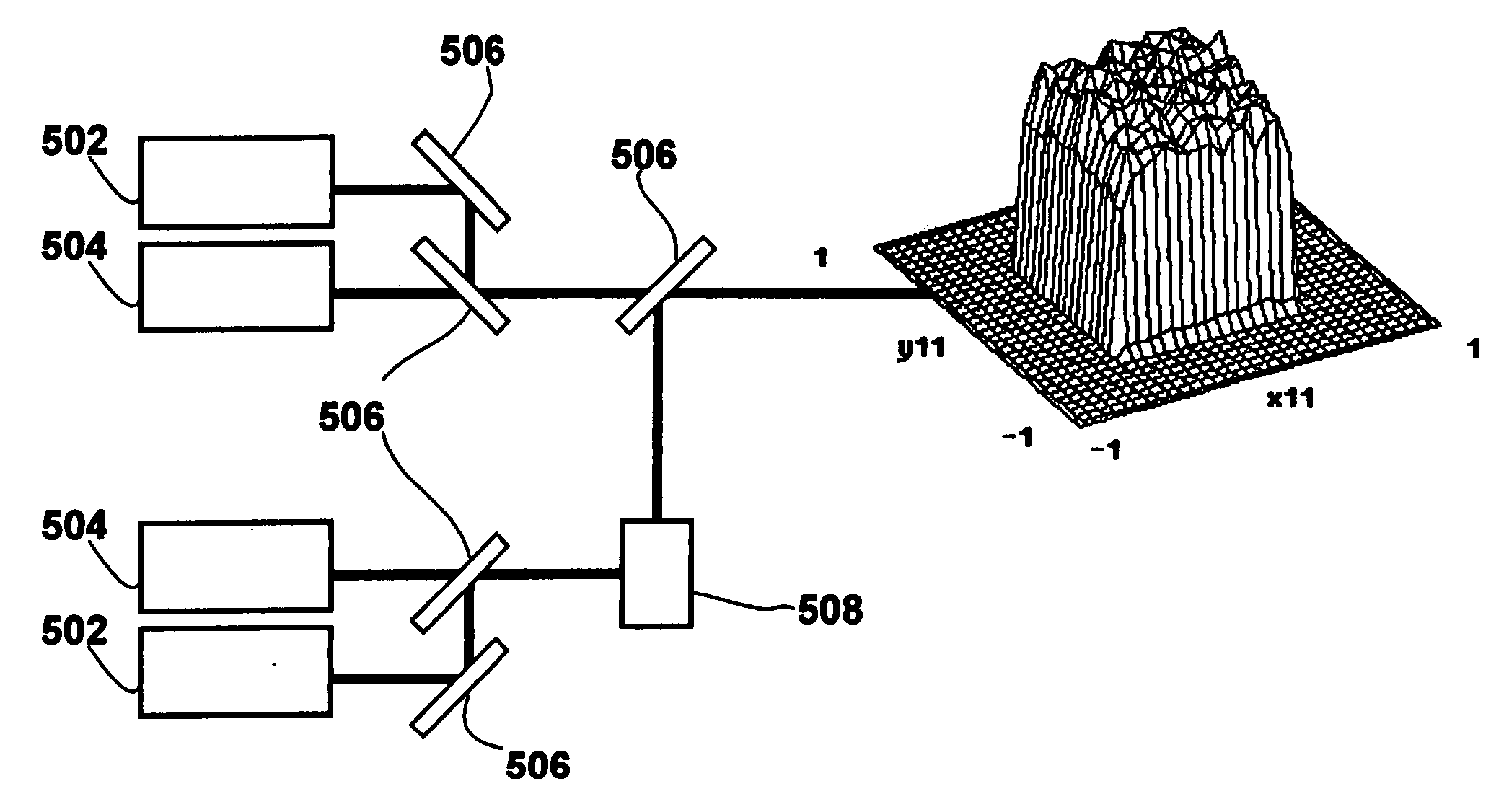
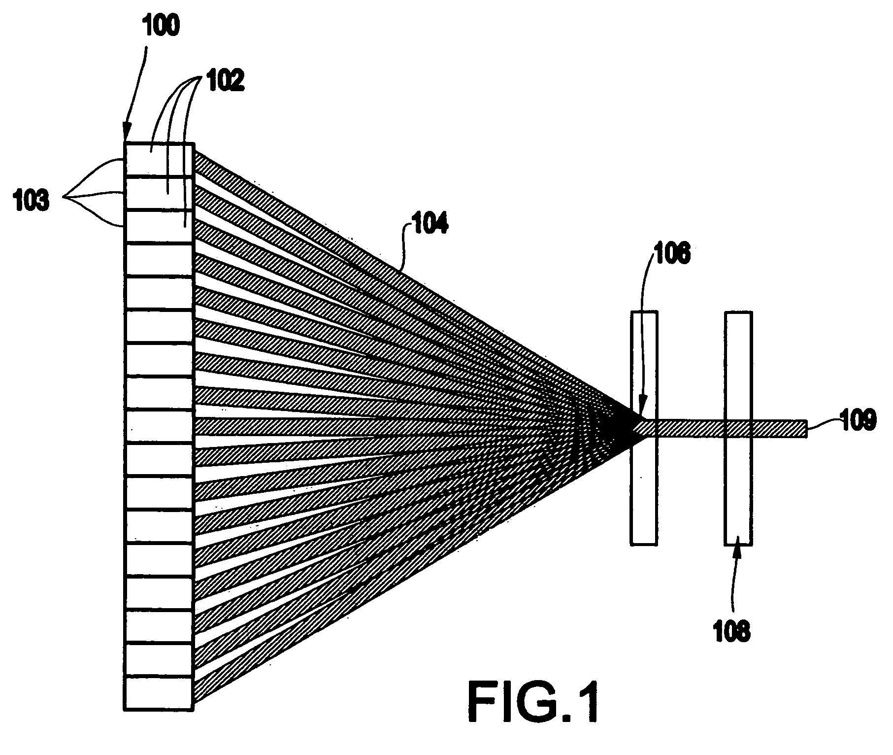
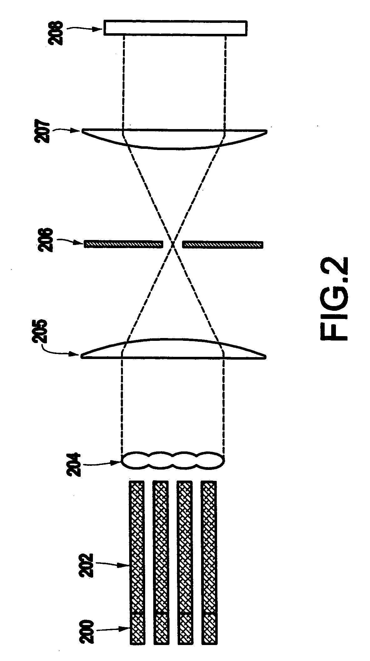
[0044] An exemplary embodiment of the present invention includes a method (and system) for building a laser diode array (e.g., a rack and stack type laser diode array according to one exemplary embodiment of the invention) using edge emitter devices with an emitter-to-emitter spacing tolerance of + / −5 microns in the X-axis and + / −50 microns in the Y-axis. The devices of the claimed invention exhibit a high electrical to optical conversion efficiency of >50% and the ability to integrate phase modulators, which are necessary for a coherent array to function (e.g., see FIG. 14).

[0045]FIG. 14 depicts exemplary phase modulators (1401) integrated into a single mode diode laser bar. The single mode diode laser bar includes a high power amplifier section 1402, an HR coating 1403 and an AR coating 1404. Arrow 1405 i...


PUM


Abstract

A method (and system) of coherently combining a plurality of diodes in an external cavity laser diode system includes adjusting the phase of the plurality of diodes to correct phase errors, wherein the adjusting the phase includes intercavity phase adjustment. The laser diode external cavity system includes an adjuster for intercavity phase adjustment.

Description

CROSS REFERENCE TO RELATED APPLICATIONS [0001] The present application is related to U.S. Provisional Patent Application No. 60 / 621,088 filed on Oct. 25, 2004, to Zediker et al., entitled “EXTERNAL CAVITY LASER DIODE SYSTEM” having client Docket No. NUV.008, which is incorporated, in its entirety, herein by reference.BACKGROUND OF THE INVENTION [0002] 1. Field of the Invention [0003] The present invention generally relates to a method and apparatus for coherently combining the outputs of laser diode sources, and more particularly to a method and apparatus for coherently coupling the output of an array of diodes in an external cavity laser diode system. [0004] 2. Description of the Related Art [0005] External cavities laser diode systems have been developed for coherently combining a plurality of laser diodes. However, most of the previous efforts resulted in only a few hundred milliwatts to Watts of power. This disclosure provides a means for scaling a high brightness laser diode sy...

Claims


Application Information

Patent Timeline
Patent Type & Authority Applications(United States)
IPC IPC(8): H01S3/13H01S3/08
CPCH01S5/06246H01S5/4062H01S5/4025H01S5/4012
Inventor ZEDIKER, MARKFAIRCLOTH, BRIANHAAKE, JOHN
Owner COHERENT INC
Why Eureka
Try Eureka