Chip using method and test chip

a technology of test chips and methods, applied in the field of test chips using methods, can solve the problems of complex processing, inability to provide efficient extraction of target components from samples, and insufficient means for plasma measurement after separation, so as to simplify the structure of the entire apparatus, simplify the process, and accurately measure the

Active Publication Date: 2007-01-04
HORIBA LTD
View PDF5 Cites 14 Cited by
  • Summary
  • Abstract
  • Description
  • Claims
  • Application Information

AI Technical Summary

Benefits of technology

[0066] The reagent is introduced into the mixing section by rotation around the same axis of rotation as the axis of the separating step and / or the measuring step. The target component separated and measured is introduced into the mixing section by rotation around the first axis of rotation, and, subsequently is mixed with the reagent. Use of the method described above allows collective performance of separation, measurement, and mixing with the reagent of the target component in the sample. Furthermore, since switching of the first axis of rotation to the second axis of rotation and the second axis of rotation to the second axis of rotation enables performance of separation, measurement, and mixing with the reagent of the sample, a simpler process can be realized.
[0067] Since the target component is accurately measured at this point, a mixed substance having a desired mixing ratio between the reagent and the target component may be obtained. As described above, performance of separation, measurement, and mixing only by means of the rotation of the chip may further simplify the structure of the entire apparatus containing the chip currently laid thereon. Since neither the sample nor the target component is removed out of the chip in steps until the sample is introduced and mixed with the reagent, contamination of the sample or the target component may be reduced. In addition, since separation and measurement may be performed in one chip, miniaturization of the chip may be achieved.
[0068] Here, introduction of the reagent is preferably performed concurrently with the separation, measurement, or mixing. Introduction of the reagent into the mixing section is performed at the time of the rotation of the chip in the separation, measurement, or mixing. Accordingly, a mixed substance may quickly be obtained.
[0069] Moreover, the method further preferably comprises the steps of: irradiating light onto the mixed substance of the target component and the reagent; and determining the target component by extracting the light after passing through the interior of the mixed substance. Light is irradiated onto the mixed substance of the reagent and the target component, and then the light is extracted after passage in order to determine the target component. Accordingly, use of the method enables collective performance of separation, measurement, mixing with the reagent, and determination of the target component in the sample, by two of the first axis of rotation and the second axis of rotation. Furthermore, performance of separation, measurement, mixing, and determination in one chip may achieve miniaturization of the chip. Since the target component is accurately measured at this point, a mixed substance having a desired mixing ratio between the reagent and the target component may be obtained. Moreover, since the target component is not removed out from the chip, contamination of the target component may be reduced to be determined accurately.

Problems solved by technology

However, the blood analyzer shown in Japanese Patent Application Publication No. 2003-83958 enables the separation of plasma as a target component by using centrifugal force generated by rotation around an axis of rotation, but does not provide means for measuring the plasma after separation.
Accordingly, the target component must be removed by a pump means in order to be introduced into an analyzer after separation, and therefore the sequential operations of separation, accurate measurement, etc. of the target component may not be performed within the same chip, leading to complicated processing.
At this point, the supernatant liquid containing the target component must be removed in a manner that enables the prevention of contamination with non-target components collected on the bottom due to centrifugal force, and thus fails to provide efficient extraction of the target component from the sample.
Accordingly, switching must be performed at least three times, i.e., switching from A to B, switching from B to A, and switching from A to B, and this is complicated.
In addition, the application of heat, such as with infrared rays, may be needed in order to remove this wax valve, leading to the need for complicated temperature control.
Furthermore, when the melting and dissolution of the wax valve results in wax being mixed into the sample, the sample and the target component may be contaminated, disabling accurate measurement and determination of the target component.

Method used


Image

  • Chip using method and test chip
  • Chip using method and test chip
  • Chip using method and test chip

Examples


first embodiment

[0151]FIG. 8A and FIG. 8B are perspective views of a test chip according to the first embodiment of the present invention.

(1) Overall Configuration of the Test Chip

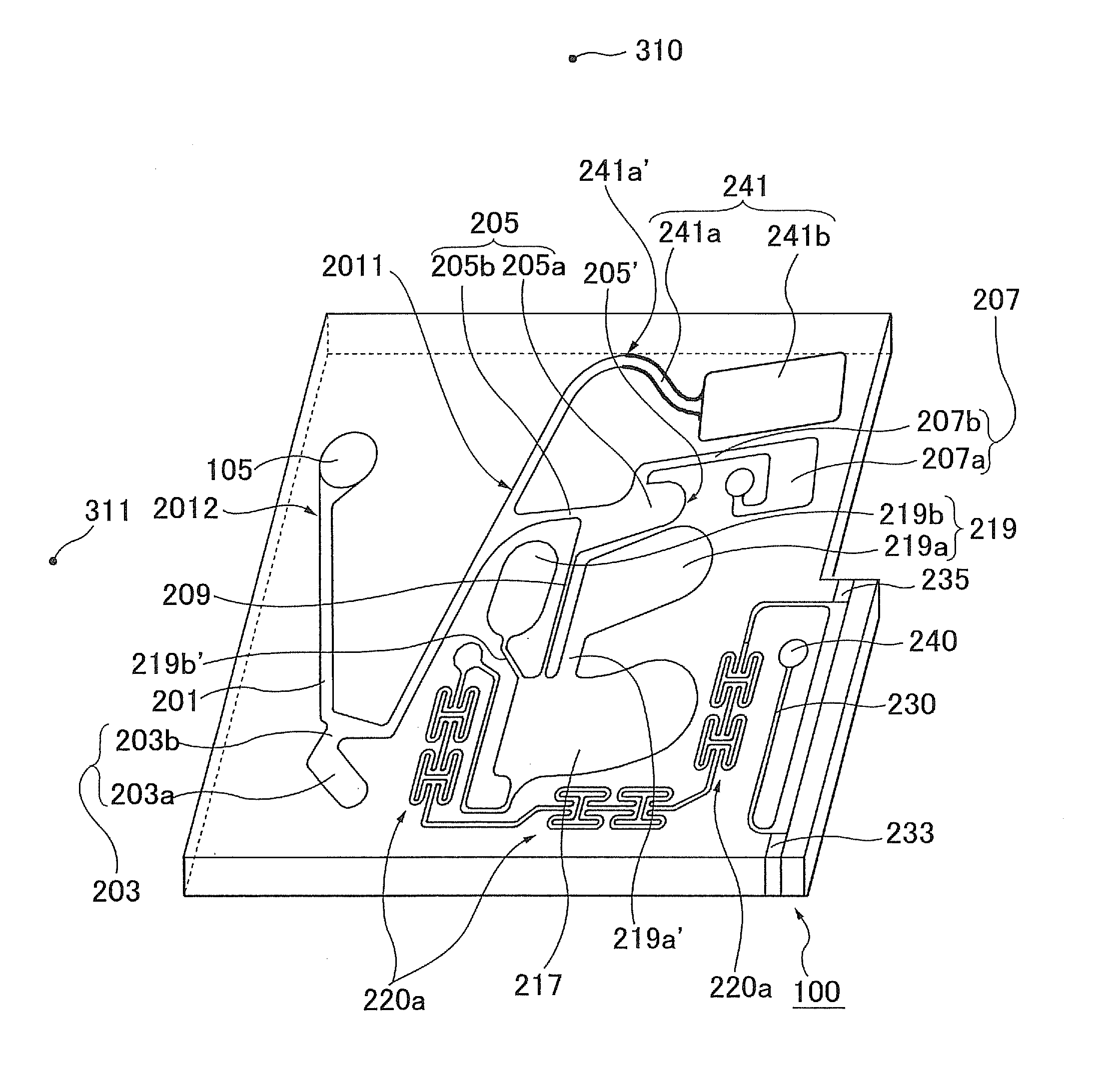
[0152] A test chip 100 of the first embodiment comprises an inlet 105 for a sample containing a target component, a centrifugal separation tube 201, a holding section (203a, 203b) 203, a first measuring section (205a, 205b) 205, a waste fluid reservoir (207a, 207b) 207, a removing tube 209, a primary mixing section 217, a reagent reservoir (219a, 219b) 219 for storing a reagent, a secondary mixing section 220 comprising a mixer section 220a, a photodetection path 230, a light inlet 233, a light outlet 235, an outlet 240, and a regulation tube (241a, 241b) 241. As shown in FIG. 10, this test chip 1 separates and measures a target component, and mixes the target component and a reagent by rotation around the first axis of rotation 310 and the second axis of rotation 320 described below.

[0153] An inlet 105 incorporates a...

second embodiment

[0206]FIG. 27 is a perspective view of a test chip according to a second embodiment of the present invention, FIG. 28 is an explanatory diagram describing the principal portion of FIG. 27, FIG. 29 is a perspective view of another test chip according to the second embodiment, and FIG. 30 is an explanatory diagram describing the principal portion of FIG. 29. The second embodiment has the same configuration as that of the first embodiment except for being able to measure an introduced reagent using a reagent measuring section 670, a discarded reagent reservoir 675, a reagent removing tube 677, and a reagent introductory section 679. Identical reference notations and numerals represent identical structural elements.

[0207] A test chip 400 of FIG. 27 comprises an inlet 105 for a sample comprising a target component, a centrifugal separation tube 201, a first holding section (203a, 203b) 203, a first measuring section (205a, 205b) 205, a waste fluid reservoir (207a, 207b) 207, a removing ...

third embodiment

[0212]FIG. 31 is a perspective view of a test chip according to a third embodiment of the present invention, FIG. 32 is a plan view of FIG. 31, and FIG. 33 shows a detecting device having the test chip of FIG. 31 placed thereon. The third embodiment has the same configuration as that of the first embodiment except that a plurality of determining sections (200a, 200b, 200c) 200 comprising a measuring section, a mixing section, etc. are provided so that a plurality of tests may be performed, and that the configuration in the vicinity of the substrate of the light inlet 233 and the light outlet 235 differs from that of the first embodiment. Identical notations and numerals represent identical structural elements.

[0213] A test chip 100 of the third embodiment comprises an inlet 105 of a sample comprising a target component, a centrifugal separation tube 201, a first holding section 203, a plurality of determining sections (200a, 200b, 200c) 200, a waste fluid reservoir 207, and a regul...


PUM

PropertyMeasurementUnit
angleaaaaaaaaaa
angle of contactaaaaaaaaaa
depthsaaaaaaaaaa

Abstract

An object of the invention is to provide a test chip which allows efficient and convenient separation and measurement. This invention provides a measuring chip for separating and measuring a target component in a sample by rotation around first and second axes of rotation. The measuring chip includes a centrifugal separation tube that centrifugally separates the target component from the sample by rotating the measuring chip around the first axis of rotation; a first holding section installed in the bottom of the centrifugal separation tube, wherein non-target components other than the target component in the sample are introduced therein by rotation around the first axis of rotation, and the first holding section holds the non-target components during rotation around the second axis of rotation; and a measuring section connected to one end of the centrifugal separation tube that measures the non-target components introduced from the centrifugal separation tube by rotation around the second axis of rotation.

Description

TECHNICAL FIELD [0001] The present invention relates to a method for using a chip in which a sample containing a target component has been introduced thereto, and to a test chip for testing the target component. BACKGROUND ART [0002] In order to diagnose hepatic and hepatobiliary disease, and alcoholic hepatopathy and to observe therapeutic processes, biochemical tests are widely carried out by sampling and measuring the concentration of enzymes in the liver, kidney, pancreas, etc., or the concentration of products thereof in the blood. Devices for conducting such biochemical tests include a blood analyzer for centrifugal separation of plasma using centrifugal force that is disclosed in Japanese Patent Application Publication No. 2003-83958. This blood analyzer performs operations in such that that it centrifugally separates serum or plasma from blood by rotating a chip with a blood sample that has been introduced therein by rotation around an axis of rotation, removing the centrifu...

Claims


Application Information

Patent Timeline
Patent Type & Authority Applications(United States)
IPC IPC(8): G01N31/22B01L3/00G01N1/00G01N1/10G01N33/48
CPCB01L3/502738B01L2400/086B01L3/502753B01L2200/0621B01L2200/10B01L2300/0654B01L2300/0672B01L2300/0803B01L2300/0816B01L2300/0864B01L2300/087B01L2400/0409B01L2400/0478B01L2400/0683B01L3/502746
Inventor HORIKE, YASUHIROYOKOGAWA, AKINORI
Owner HORIBA LTD
Why Eureka
Try Eureka