Burner, gas turbine combustor, burner cooling method, and burner modifying method

Inactive Publication Date: 2007-01-04
HITACHI LTD
View PDF19 Cites 75 Cited by
  • Summary
  • Abstract
  • Description
  • Claims
  • Application Information

AI Technical Summary

Benefits of technology

[0022] According to the present invention, even when the mixed fuel containing at least one of hydrogen and carbon monoxide is used as fuel, the flame temperature can be reduced by increasing a fuel concentration near the nozzle surface, whereby the metal te

Problems solved by technology

However, after the shift to the gas combustion mode using only the mixed fuel, there is a fear that a flame may become apt to come close to a nozzle surf

Method used


Image

  • Burner, gas turbine combustor, burner cooling method, and burner modifying method
  • Burner, gas turbine combustor, burner cooling method, and burner modifying method
  • Burner, gas turbine combustor, burner cooling method, and burner modifying method

Examples


first embodiment

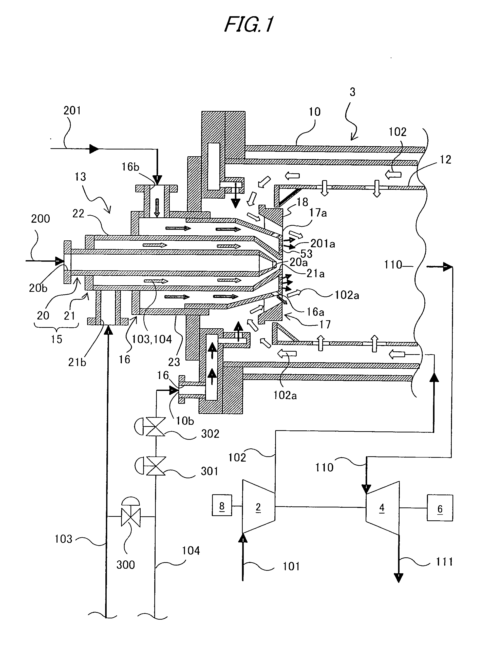
[0033]FIG. 1 is a schematic view of a gas turbine plant equipped with a burner related to the present invention.

[0034] The gas turbine plant equipped with the burner related to this first embodiment comprises an air compressor 2, a combustor 3, a turbine 4, a generator 6, a startup motor 8 for driving a gas turbine, and so on. Inlet air 101 is compressed in the air compressor 2, and compressed air 102 from the air compressor 2 is burned in the combustor 3 together with fuel 200 and 201. When burned gas 110 from the combustor 3 is supplied to the turbine 4, the turbine 4 produces torque with the burned gas 110, and the torque produced by the turbine 4 is transmitted to both the air compressor 2 and the generator 6. The torque transmitted to the air compressor 2 is used as power for compressing air, and the torque transmitted to the generator 6 is converted to electrical energy.

[0035] While the generator 6 is shown as being load equipment in FIG. 1, a pump, etc. may also be used as t...

second embodiment

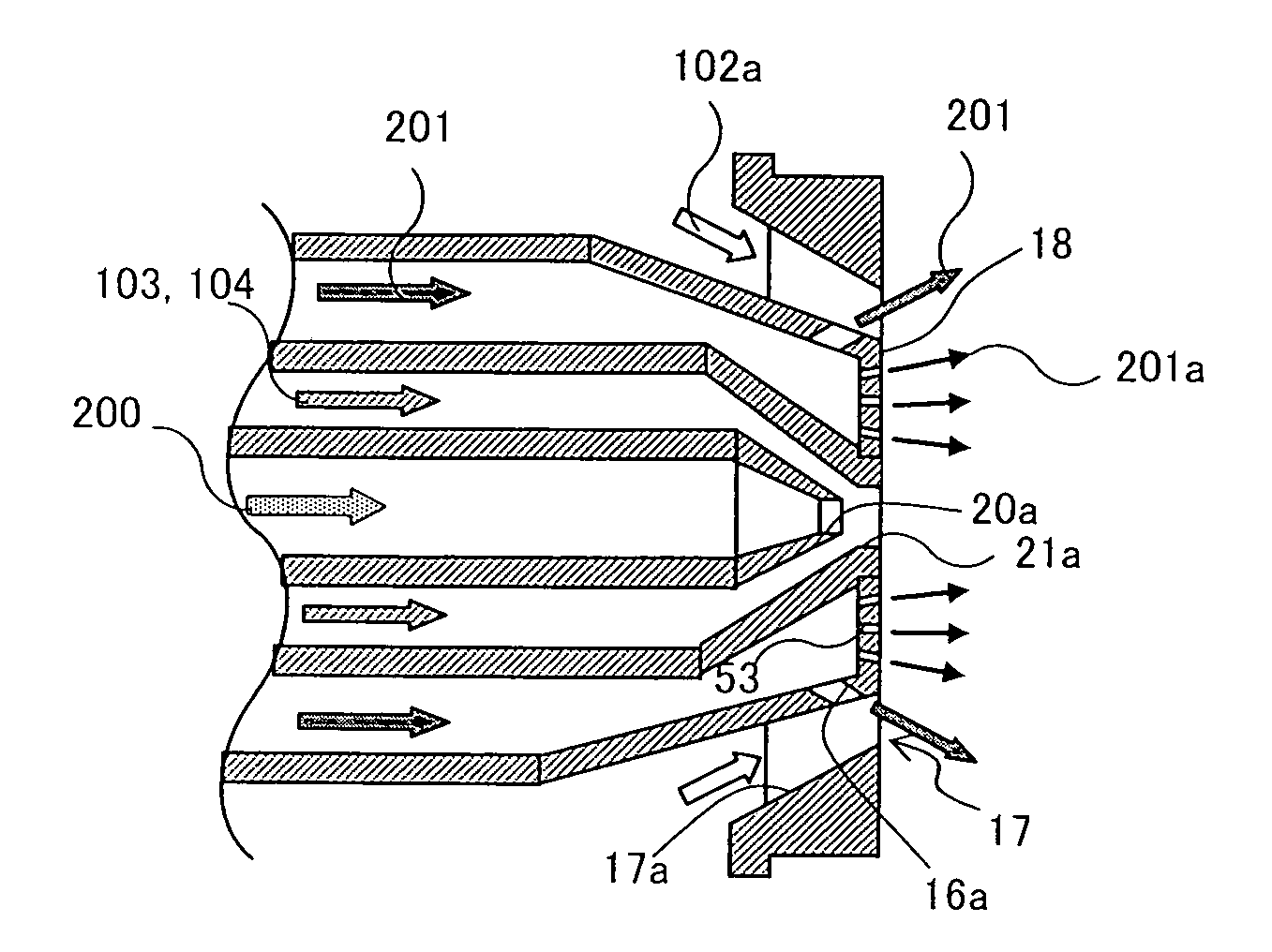
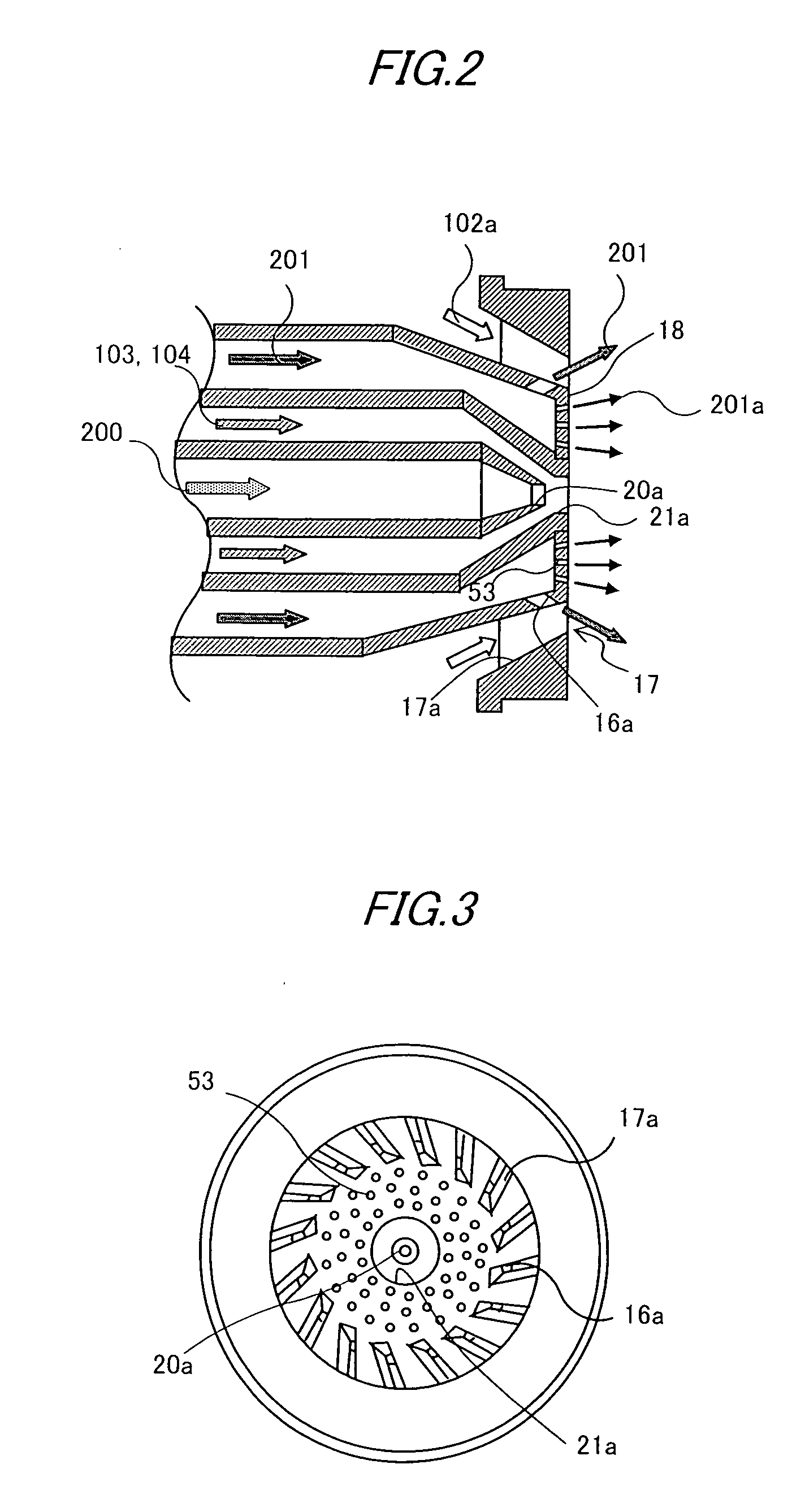
[0065] In the burner shown in FIGS. 4 and 5, the injection ports 16a are formed at the inner peripheral side of the flow passages 17a of the air swirler 17, and the fuel nozzle 15 for startup is disposed at the center of the air swirler 17 in the radial direction. Stated another way, the burner has the same structure as that shown in FIGS. 2 and 3 except for that the cooling holes 53 are omitted. A rise of the metal temperature at the nozzle surface 18 can also be suppressed even with the burner having the structure that the cooling holes 53 are not formed and the fuel concentration in the area near the nozzle surface 18 cannot be enriched with the absence of the cooling holes 53 for introducing a part of the gas fuel.

[0066]FIG. 6 is a schematic view of a gas turbine plant equipped with the burner, shown in FIGS. 4 and 5, according to the second embodiment of the present invention.

[0067] As in the gas turbine plant shown in FIG. 1, the gas turbine plant shown in FIG. 6 employs the...

third embodiment

[0070]FIG. 9 is a schematic view of a gas turbine plant equipped with a burner according to the present invention, the plant including a system for purging liquid fuel residing in a nozzle for startup.

[0071] In the first and second embodiments, the liquid fuel 200 is used for the startup of the gas turbine, and the supply of the liquid fuel 200 is stopped after the operating mode is shifted to the gas combustion mode using only the mixed fuel in a certain load condition. In such a process, if the liquid fuel 200 resides in the liquid fuel nozzle 20, there occurs a phenomenon (coking) that the liquid fuel nozzle 20 is heated by heat from the flame and the residing liquid fuel 200 is solidified in the nozzle. To avoid such a phenomenon, after completion of the shift to the gas combustion mode using only the mixed fuel, gas such as nitrogen is supplied to the liquid fuel nozzle 20 to purge the residing liquid fuel 200 into the combustion chamber, to thereby prevent the flow passage of ...


PUM


Abstract

In a burner for injecting mixed gas fuel containing at least one of hydrogen and carbon monoxide into a combustion chamber of a gas turbine combustor, the burner includes a fuel nozzle for startup from which liquid fuel is injected into the combustion chamber, and a mixed fuel nozzle disposed around the fuel nozzle for injecting the mixed gas fuel. An air swirler is disposed at a downstream end of the mixed fuel nozzle and has a plurality of flow passages from which compressed air is injected into the combustion chamber, and the mixed fuel nozzle has injection ports disposed in the inner peripheral side of the flow passages of the air swirler. Cooling holes formed in the nozzle surface and positioned to face the combustion chamber introduce a part of the mixed gas fuel injected from the mixed fuel nozzle into the combustion chamber.

Description

BACKGROUND OF THE INVENTION [0001] 1. Field of the Invention [0002] The present invention relates to a burner using mixed fuel containing at least one of hydrogen and carbon monoxide, and also relates to a gas turbine combustor, a burner cooling method, and a burner modifying method. [0003] 2. Description of the technology [0004] Recently, the varieties of fuel for use in gas turbines have been increased. The use of multi-component mixed gas fuel containing hydrogen, carbon monoxide, etc. (hereinafter referred to simply as “mixed fuel”) has been proposed in addition to conventional primary fuel for gas turbines, such as LNG (liquefied natural gas), light oil, and A-heavy oil. Such mixed fuel has a higher flame temperature than LNG. In particular, hydrogen has a wider flammable range and a faster burning velocity and is easy to burn. [0005] LNG is burned primarily by employing a premixed combustion system. However, when the mixed fuel is burned by employing the premixed combustion sy...

Claims


Application Information

Patent Timeline
IPC IPC(8): F23D14/62
CPCF23R3/28F23R3/04F23R3/283F23R3/286F23R2900/00002F23L2900/07002F23R2900/00016F23R2900/03041F23R3/343F23K2401/10F23K2400/10
Inventor KOIZUMI, HIROMIINOUE, HIROSHISASAO, TOSHIFUMITAKEHARA, ISAO
Owner HITACHI LTD
Why Eureka
Try Eureka