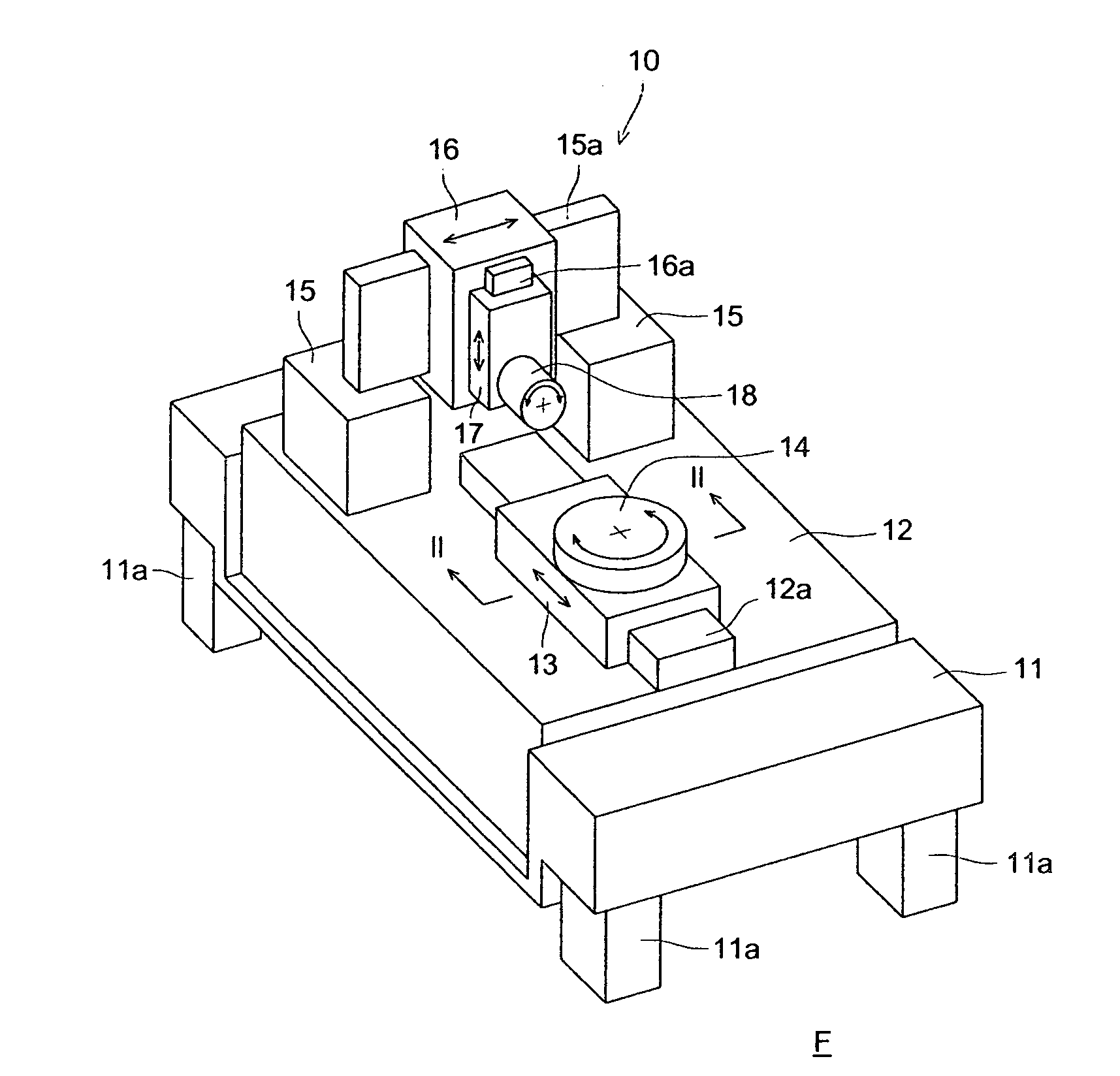
Machining apparatus

a technology of machining apparatus and machining chamber, which is applied in the direction of auxillary equipment, manufacturing tools, electric/magnetic/electromagnetic heating, etc., can solve the problems of high-accuracy machining, large heat generation of this motor, and longer machining time, so as to achieve high-efficiency machining

Inactive Publication Date: 2007-01-11
KONICA MINOLTA OPTO
View PDF15 Cites 3 Cited by
  • Summary
  • Abstract
  • Description
  • Claims
  • Application Information

AI Technical Summary

Benefits of technology

[0018] Further, in a machining apparatus having a degree of freedom of machining of three axes or greater, it is carried out in most cases, a shaping machining, that is, a machining in which, in association with a reciprocating movement with respect to one axis, another movement with respect to another axis is carried out, which moves a tool along the cross-sectional shape of a free surface, and by the three-dimensional accumulation of a number of movements of the tool one above another, a curved surface is generated by cutting, grinding, etc.; however, this shaping machining takes a very long time, particularly, in generating a high-accuracy optical surface, even for a work piece of a size of an order of several centimeters, it is general that a machining time of several ten hours is required for it. Accordingly, it is very important for the purpose of carrying out a high-accuracy generating of an optical surface, how to make the machining difficult to undergo the influence of the change of the environment such as the temperature during the period of time of machining, or to make the variation of the environment during the machining smaller by shortening the machining time.
[0019] In contrast with this, according to this invention, even in a case where a temperature variation occurs, because the thermal expansion coefficient can be suppressed at a low value in comparison with a steel or the like, by forming the above-mentioned first machining table of a ceramic material, the accuracy of machining can be maintained, while the machining time can be shortened because the acceleration and deceleration ability is raised by the workbench being made light-weighted. Further, because it is enough if the power of the motor or the like as an axis member driving means for driving the above-mentioned first workbench is low, energy saving can be achieved and also the heat generation can be suppressed; therefore, a higher-accuracy machining can be actualized.
[0021] In contrast with this, according to this invention, by forming the above-mentioned first workbench of a ceramic material, in comparison, for example, with a conventional workbench made of cast iron, its weight can be reduced by a large margin and its Young's modulus can be made two times larger; therefore, bending caused by the self-weight can be suppressed, and it is obtained a structure such that a resonance or the like is hard to produce because the specific frequency of the vibration is made higher.

Problems solved by technology

Therefore, because the workbench becomes heavy, and the power of a servomotor required for driving this becomes high, there has been a problem that the quantity of heat generation from this motor becomes large.
Further, because it has not been possible to move the workbench at a high speed, there has been also a problem that the speed of machining becomes slow, which makes the machining time longer, and if a variation of the environment such as the temperature occurs, the deformation of the workbench due to thermal expansion and the drift of position of a work piece and a tool become large, which makes a high-accuracy machining difficult.
; however, this shaping machining takes a very long time, particularly, in generating a high-accuracy optical surface, even for a work piece of a size of an order of several centimeters, it is general that a machining time of several ten hours is required for it.

Method used


Image

  • Machining apparatus
  • Machining apparatus
  • Machining apparatus

Examples


first embodiment

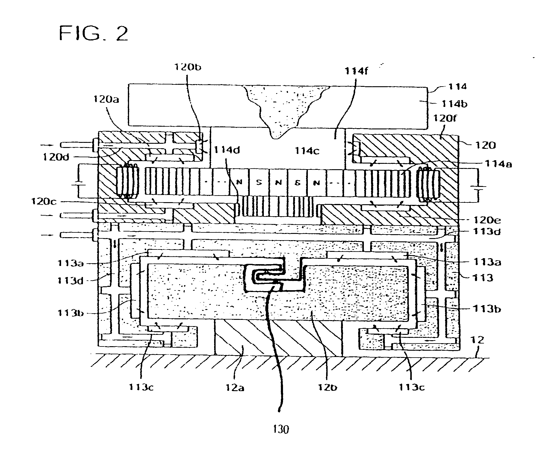
[0029] A second embodiment of the invention is a variant of the first embodiment, wherein the aforesaid ceramic material has a coefficient of linear expansion of 5×10⁻⁶ K−1 or less; therefore, as compared to cast iron, its thermal expansion can be suppressed to be low by half or less; therefore, the accuracy of machining can be maintained secured while the acceleration ability is made higher owing to its weight being made lighter, which makes it possible to shorten the machining time.

second embodiment

[0030] A third embodiment of the invention is a variant of the first or the second embodiment, wherein the aforesaid ceramic material contains silicon nitride of 50% or more by weight and has a specific weight of 4 g / cm3; therefore, the weight of the aforesaid workbench becomes a half or less of a conventional one, and even if the power of the axis member driving means for driving it (for example, a motor) is the same, the acceleration can be made two times theoretically. Accordingly, the time to reach the target machining speed is reduced by half, and the quantity of heat generation is also halved for that reason. Further, because it becomes fast the response of the servomechanism for detecting the position of the aforesaid first workbench and applying a feedback to the driving motor, the accuracy of movement and the accuracy of positioning of said first workbench are made higher. From this viewpoint, the specific weight may be better if it is smaller; however, because a high Young...

seventh embodiment

[0035] the invention is a variant of one of the first to sixth embodiments further comprising a measurement means having a resolution of 10 nm or less for measuring the position of the aforesaid first workbench; therefore, the response of the servomechanism which detects the position of the above-mentioned first workbench to give a feedback to the axis member driving means is made faster, which makes higher the accuracy of movement and the accuracy of positioning of the above-mentioned first workbench.


PUM

PropertyMeasurementUnit
Young's modulusaaaaaaaaaa
frequencyaaaaaaaaaa
viscosityaaaaaaaaaa

Abstract

A machining apparatus for conducting at least one of a cutting process and a grinding process, comprises a stationary base; and a working device mounted on the stationary base and having a degree of freedom of more than two axes to conduct at least one of a cutting process and a grinding process, the working device comprising a first working bench which is formed of a ceramic material and is movable linearly with a degree of freedom of not less than one axes or more while holding a work piece or a tool.

Description

CROSS-REFERENCE TO RELATED APPLICATIONS [0001] This is a division of application Ser. No. 10 / 827,579, filed Apr. 19, 2004, which claims priority from Japanese Patent Application No. 2003-292289, filed Aug. 12, 2003 and Japanese Patent Application No. 2003-324674, filed Sep. 17, 2003. The entire content of application Ser. No. 10 / 827,579 is incorporated herewith by reference. BACKGROUND OF THE INVENTION [0002] 1. Field of the Invention [0003] This invention relates to a machining apparatus having a degree of freedom of machining of three axes or greater. [0004] Herein, the term “axes” or “an axis” is defined as a portion of a machining apparatus that functions as the reference line or plane of a movement for machining, for example, the rotary shaft of a swivel table, the slideway of a slide table, etc. The degree of freedom of movement for machining is one for each of the “axes”. [0005] 2. Description of the Related Art [0006] A machining apparatus for applying cutting machining, gri...

Claims


Application Information

Patent Timeline
Patent Type & Authority Applications(United States)
IPC IPC(8): B23P23/00B23Q1/26B23Q1/38B23Q1/00B23Q1/48B24B13/00B24B13/06
CPCB23Q1/38B23Q1/4852B24B13/06Y10T409/309576Y10T409/305656Y10T29/511Y10T409/304312Y10T29/5114B23Q2220/004H05B6/6482H05B6/76
Inventor HOSOE, SHIGERU
Owner KONICA MINOLTA OPTO
Why Eureka
Try Eureka