Method for manufacturing a fuel-cell stack and terminal plate

a technology of fuel cells and terminal plates, which is applied in the direction of sustainable manufacturing/processing, secondary cell servicing/maintenance, and final product manufacturing, etc., can solve the problems of easy detachment of evaporation, difficult to form a film sheet structure, and poor electrical insulation properties, and achieve excellent adhesion and shape adaptability, good electrical insulation properties, and light weight

Inactive Publication Date: 2007-01-11
AISIN TAKAOKA CO LTD +1
View PDF8 Cites 21 Cited by
  • Summary
  • Abstract
  • Description
  • Claims
  • Application Information

AI Technical Summary

Benefits of technology

[0029] According to the fuel-cell stack of the present invention (aspects 1 and 3), the insulating resin layer that is formed on the end plates or terminal plates by an electro-deposition coating method displays good electrically insulating properties even for a relatively thin film so that insulating plates can be discarded and thus the fuel-cell stack can be made lightweight and downsized. Particularly, the insulating resin layer formed by an electro-deposition method displays excellent adhesion and shape adaptability to the plate substrate, and has uniform film thickness and continuity. Hence, the insulating resin layer hardly suffers from damages such as peeling of the film, pin holes, cracking of the film and the like even when the surface of the substrate has a complex concavo-convex shape, and enables stable maintaining of the electrically insulating performance.
[0030] Moreover, when curved surfaces are formed on the edge (or corner) portions of the end plates or terminal plates that are formed by the opposing surface and the non-parallel surfaces intersecting with the opposing surface in a way that an insulating resin layer is continuously formed over the opposing surface, curved surface(s) and non-parallel surface(s) of the plate, edges (corners), which may start damages due to the concentration of internal stress (residual stress) of that insulating resin layer, do

Problems solved by technology

However, the above evaporation method had problems in that it was subject to occurrence of insulation defects due to pin holes that were caused by resin particles, air bubbles and the like, and another problems in that adherence defects, such as easy detachment of the evaporation-coated resin due to its fragility, occurred on the edges and corners of the generally rectangular-shaped end plates (refer to paragraph of patent document 2).
However, drawbacks are also found in the end plates having the insulating film sheet structure of patent document 2.
Therefore, in the case where the end plate itself is formed into a complex shape such as by giving the end plate body a minute concavo-convex shape, there is a problem in that it is difficult to form a film sheet structure beforehand having a corresponding shape.
In a fuel cell, there is a tendency for the shape of the end plate to become complex corresponding with the multi-functionality of the plate material, and it is not easy to apply the art of patent document 2 to the e

Method used


Image

  • Method for manufacturing a fuel-cell stack and terminal plate
  • Method for manufacturing a fuel-cell stack and terminal plate
  • Method for manufacturing a fuel-cell stack and terminal plate

Examples


example 1

Example of an End Plate

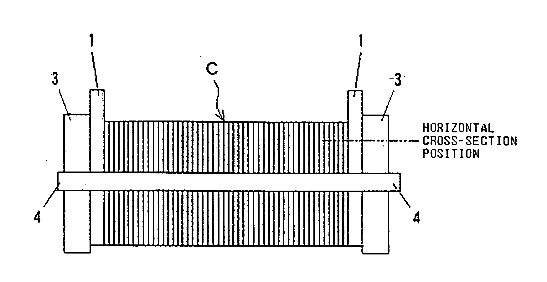
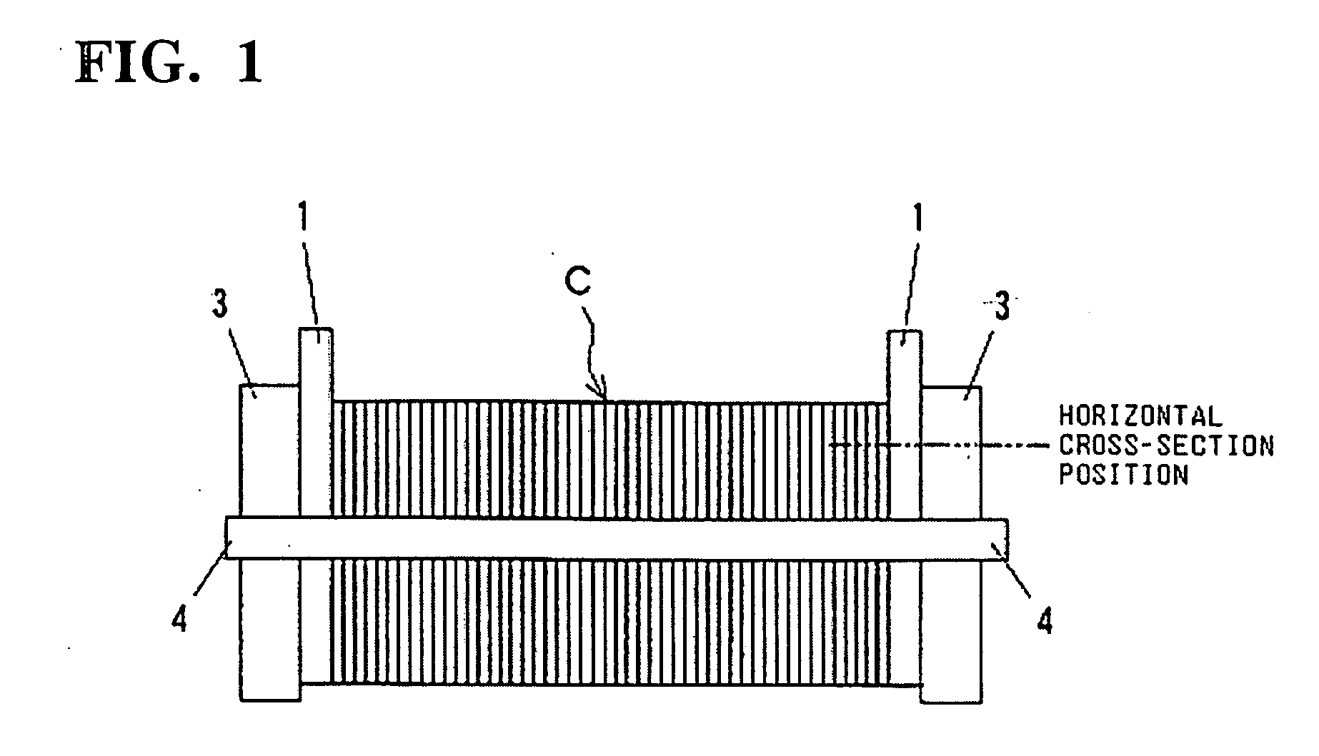
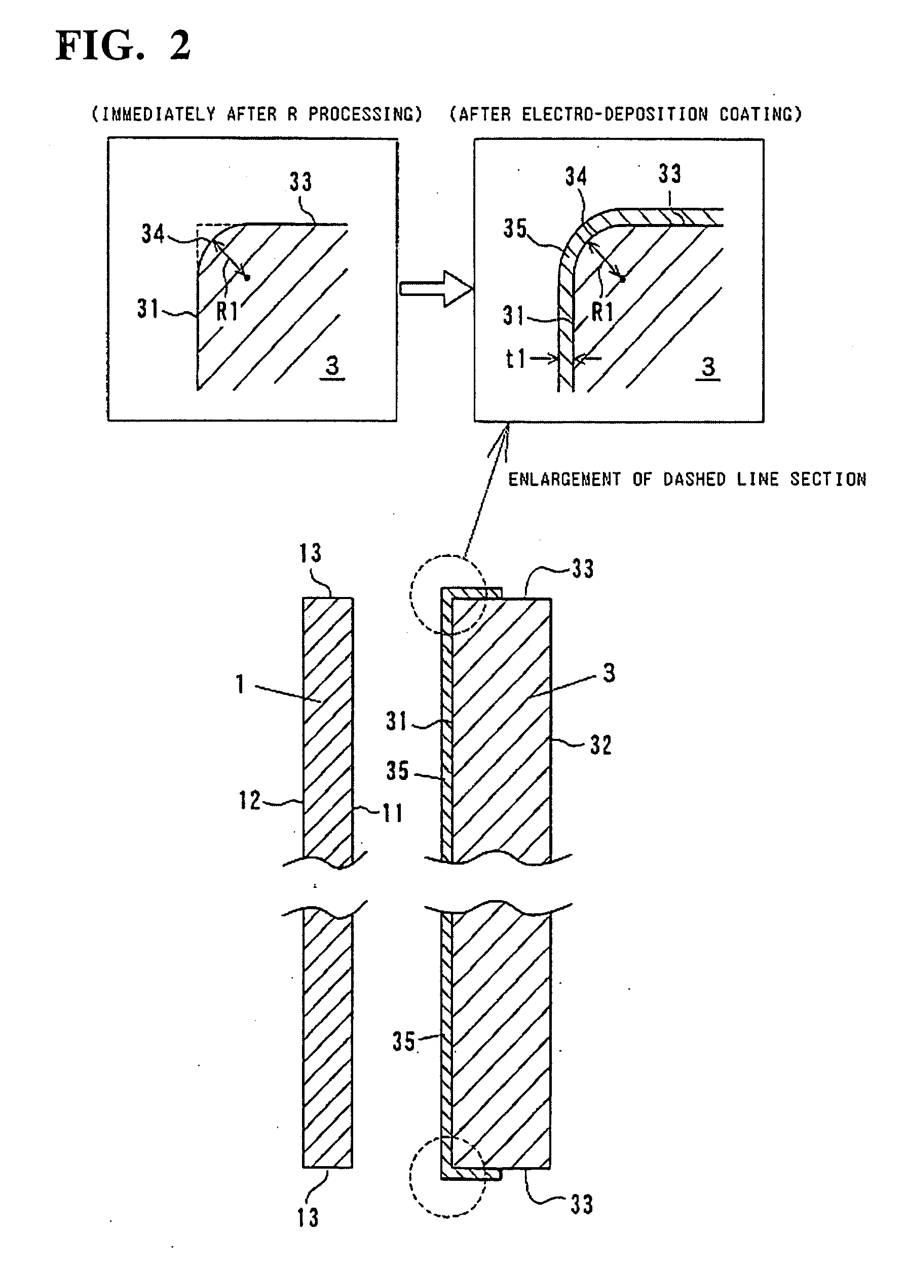
[0061] A stainless steel (SUS316) plate member was prepared as an end plate 3. This stainless steel plate member was formed into a relatively flat rectangular shape having the dimensions, 300 mm (height)×200 mm (width)×20 mm (thickness) approximately. As shown in FIG. 2, this rectangular-shaped end plate 3 has an opposing surface 31 (inner surface) facing to a terminal plate 1, and an opposite surface 32 (outer surface) on the opposite side of the opposing surface 31, and four peripheral side surfaces 33 that define four sides of these two surfaces. Each of the four peripheral surfaces 33 intersects with the opposing surface 31 and opposite surface 32 at right angles.

[0062] First, R processing was performed for the edge-shaped edge (or corner) portions that are formed by the opposing surface 31 of this rectangular-shaped end plate, and each of the peripheral surfaces 33 that intersects with the opposing surface at right angles. R processing was accomplished ...

example 2

Example of a Terminal Plate

[0065] An aluminum alloy plate member was prepared as a terminal plate 1. This aluminum alloy plate member was formed into a relatively flat rectangular shape having the dimensions, 300 mm (height)×200 mm (width)×2 mm (thickness), approximately. As shown in FIG. 3, this rectangular-shaped terminal plate has an opposing surface 11 (outer surface) that faces the end plate 3 and an opposite surface 12 on the opposite side (inner surface) of the opposing surface 11, and four peripheral side surfaces 13 that define the four sides of these two surfaces. Each of the four peripheral surfaces 13 intersects with the opposing surface 11 and opposite surface 12 with at right angles.

[0066] First, R processing was performed for the edge-shaped edge portions that are formed by the opposing surface 11 of this plate-shaped terminal plate, and each of the peripheral surfaces 13 that intersects with the terminal plate at right angles. R processing was accomplished by immer...


PUM

PropertyMeasurementUnit
Thicknessaaaaaaaaaa
Thicknessaaaaaaaaaa
Thicknessaaaaaaaaaa

Abstract

A fuel-cell stack is provided wherein an insulating resin layer having good electrical insulation characteristics is inserted between a terminal and end plate, so that an insulating plate is discarded so as to make the same more lightweight and downsized. It comprises a battery-cell group wherein a plurality of battery cells and separators are arranged; and terminal plates 1 and end plates 3 that are arranged on each end portion of the battery-cell group. The end plates 3 are formed as metal plate members having surfaces 31 opposing to the terminal plates 1. A polyimide film 35 is formed as an insulating resin layer at least on the opposing surface 31 of the end plate 3 for electrically insulating between the end plate 3 and terminal plate 1 by an electro-deposition coating method.

Description

FIELD OF THE INVENTION [0001] The present invention relates to a fuel-cell stack, particularly to improvements in construction of an electrical insulation between a terminal plate and an end plate that are located on both ends of the fuel-cell stack. The present invention also relates to a method for manufacturing a terminal plate that comprises such electrical insulation construction. BACKGROUND OF THE INVENTION [0002] As shown in FIG. 4, a conventional fuel-cell stack comprises: a battery cell group C, in which a plurality of battery cells and separators are alternately arranged and connected in series; and end-plate groups, which are located on both ends of the battery-cell group C and are each made up of terminal plate 1, insulation plate 2 and end plate 3; and the fuel-cell stack is constructed so that these groups are connected by a connection member 4 (for example, refer to patent document 1). The end plates 3 serve the purpose of directly receiving the tightening force of th...

Claims


Application Information

Patent Timeline
IPC IPC(8): H01M4/02H01M8/24
CPCH01M8/0206H01M8/0221Y02E60/50H01M8/2465H01M8/0228Y02P70/50
Inventor MAEDA, MASASHIMATSUKAWA, MASANORINISHIDA, TSUNEMASAKATO, CHISATOTAKESHITA, NAOHIRO
Owner AISIN TAKAOKA CO LTD
Why Eureka
Try Eureka