
Total Fluid Conductivity Sensor System and Method

a technology of fluid conductivity and sensor system, which is applied in the direction of fluid resistance measurement, instruments, inductances, etc., can solve the problems of increasing difficulty in environmental monitoring, corrosion and fouling of metal electrodes in contact with fluid, and easy corrosion of metal electrodes in fluid contact. , to achieve the effect of low power consumption, convenient integration with other systems, and convenient packaging

Inactive Publication Date: 2007-01-11
UNIV OF SOUTH FLORIDA
View PDF6 Cites 23 Cited by
  • Summary
  • Abstract
  • Description
  • Claims
  • Application Information

AI Technical Summary

Benefits of technology

[0015] In a specific embodiment, the first conductive elements and the second conductive elements are gold metallized, thereby providing low series resistance and high resistance to corrosion in the fluid.
[0023] As such, the present invention provides an embedded sensor that can be easily packaged, fitted to a buoy and deployed in underwater applications. The toroidal type sensors in accordance with the present invention are not prone to corrosion and fouling. The embedded design of the coils and sensing circuitry allow the sensor to be easily integrated with other systems. An integrated thermistor mounted on the coil allows for in-situ temperature monitoring and can be used for compensation. The design of the conductivity sensor in accordance with the present invention allows for low power consumption.

Problems solved by technology

Harsh conditions make environmental monitoring a very challenging task.
The ocean is an example of an environment in which salinity, temperature and pressure conditions result in a corrosive medium, making the task of environmental monitoring increasingly difficult.
One of the main problems associated with this prior art method is that corrosion and fouling of the metal electrodes in contact with the fluid commonly occurs.
The primary performance limitation of a ferrite core toroid is the loss due to the induction of eddy current.
One area that remains a challenge to miniaturize are radio frequency (RF) circuits, such as those used in cellular telephones, wireless modems, and other types of communication equipment.
The problem is the difficulty in producing a good inductor in silicon technologies that is suitable for RF applications.
One way to reduce this effect is to use wide metal line-widths, however, this increases the inductor area and the parasitic capacitance associated with the structure.
The larger inductor area limits the miniaturization that can be achieved, and the parasitic capacitance associated with the larger area decreases the self-resonance frequency of the inductor, thereby limiting its useful frequency range.
Also, since the Q is directly proportional to frequency and inversely proportional to the series loss of the inductor, the metal line widths cannot be chosen arbitrarily large.

Method used


Image

  • Total Fluid Conductivity Sensor System and Method
  • Total Fluid Conductivity Sensor System and Method
  • Total Fluid Conductivity Sensor System and Method

Examples


Embodiment Construction

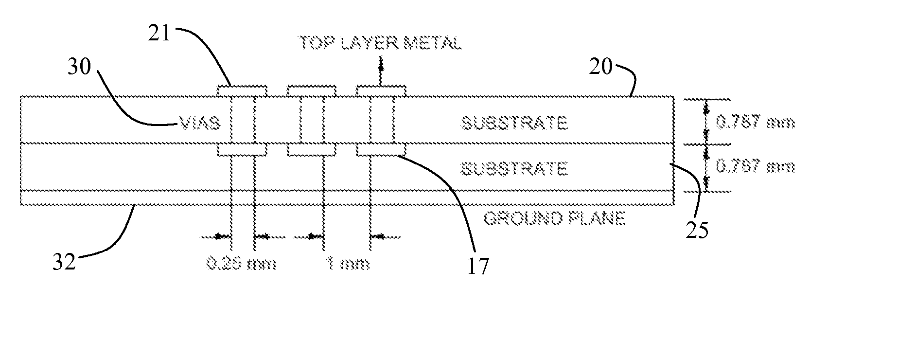
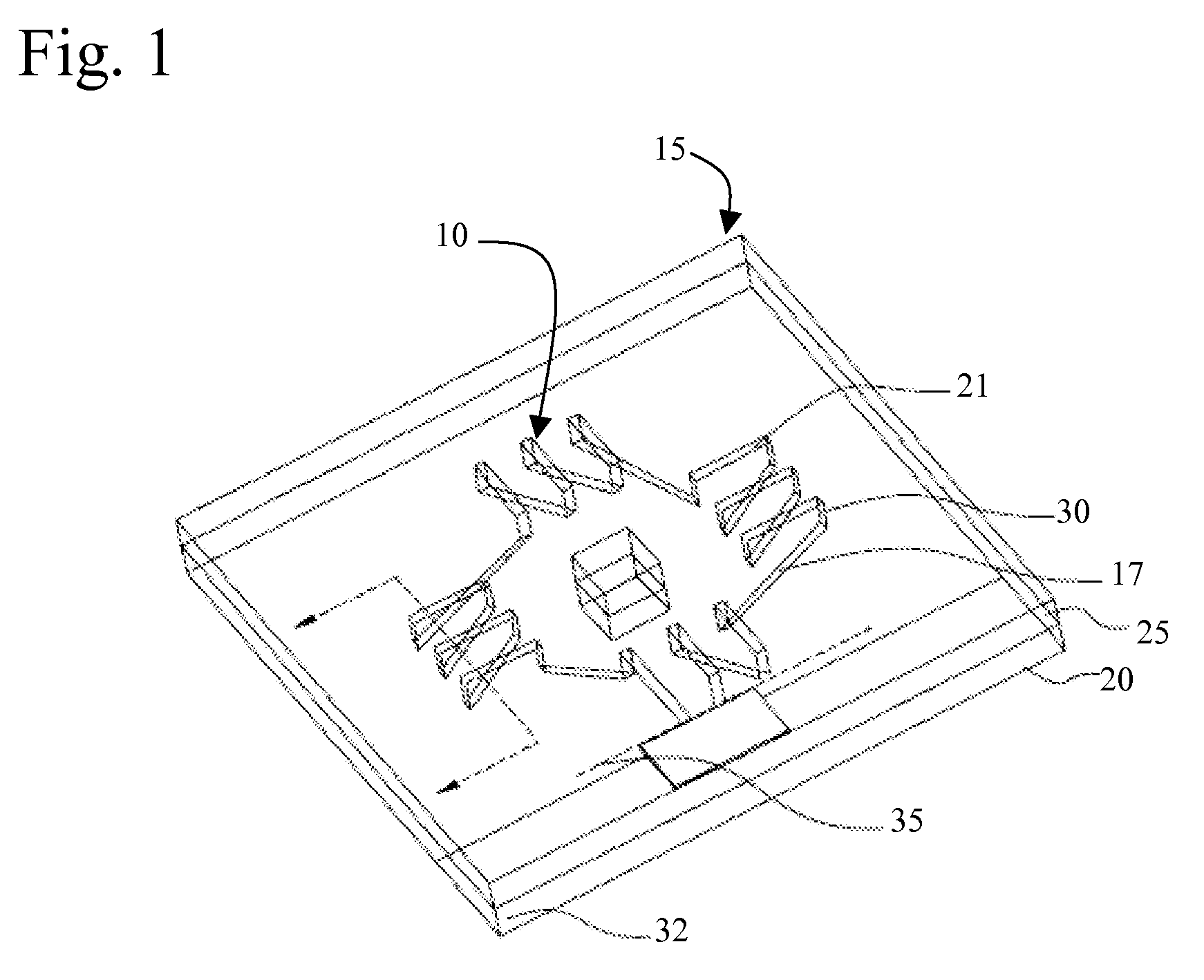
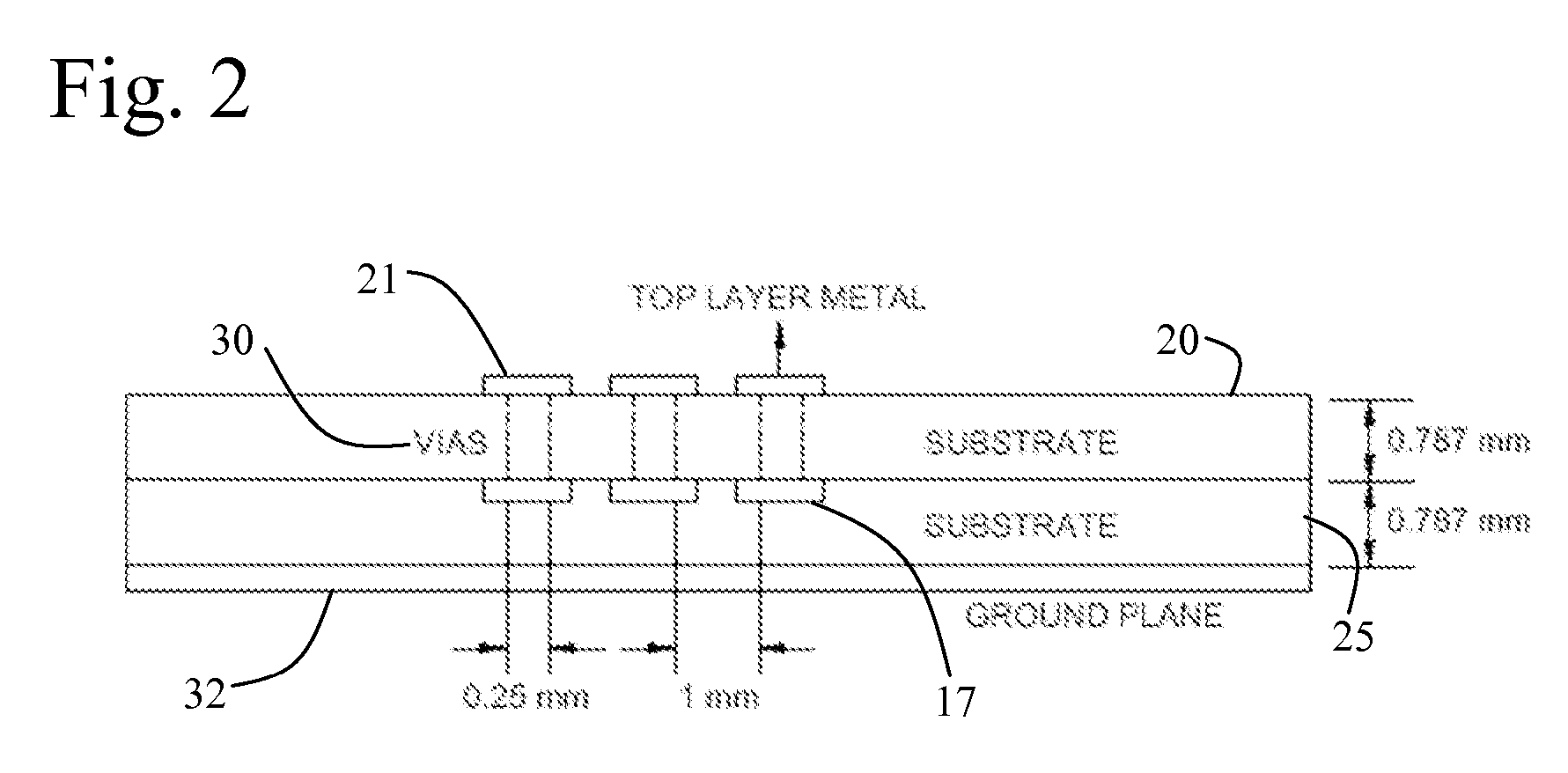
[0039] With reference to FIG. 1, each of the toroidal coils 10 in accordance with the present invention are embedded in a printed circuit board 15. The printed circuit board has a ground plane 32 and the coil windings are laid out as microstrip lines 17 on a first substrate 20 and microstrip lines 21 on a second substrate 25 and interconnections are formed to the backside of the board using plated thru vias 30. The pair of coils are then held in close proximity to each other inside the fluid. As such, a toroidal coil is formed having a core of dielectric material. In a particular embodiment, 10 mil line widths and 12 mil minimum via hole dimensions are used to suit the processing parameters typical of printed circuit board manufacturers. The toroidal coil is then connected to a 50 ohm feed line 35 for performing the conductivity measurements utilizing a radio frequency phase detector. In a specific embodiment the printed circuit board layers are 31-mil thick FR4 layers.

[0040]FIG. 2...


PUM


Abstract

The present invention provides an apparatus and method for measuring the conductivity of a fluid employing the differential radio frequency phase detection between two embedded toroidal coils.

Description

CROSS REFERENCE TO RELATED APPLICATIONS [0001] This application claims priority to currently pending U.S. Provisional Patent Application 60 / 595,267, entitled, “Contact-less Fluid Conductivity Sensor Based on Radio Frequency Detection”, filed Jun. 20, 2005.STATEMENT OF GOVERNMENT INTEREST [0002] This invention was made with Government support under Grant No. N00014-98-1-0848 awarded by the Office of Naval Research. The Government has certain rights in the invention.BACKGROUND OF THE INVENTION [0003] Harsh conditions make environmental monitoring a very challenging task. Sensors deployed for environmental monitoring must adhere to stringent quality requirements to ensure reliable data output. The ocean is an example of an environment in which salinity, temperature and pressure conditions result in a corrosive medium, making the task of environmental monitoring increasingly difficult. [0004] Conductivity, temperature and depth (CTD) data of the ocean are important parameters for oceano...

Claims


Application Information

Patent Timeline
IPC IPC(8): H01F27/28
CPCG01N27/023G01N27/06G01N27/07H05K1/165H01F5/003H01F17/0033H05K1/0272G01R27/22
Inventor WELLER, THOMAS M.FRIES, DAVID P.NATARAJAN, SARAVANA P.
Owner UNIV OF SOUTH FLORIDA
Learn More