However, there are several fundamental problems associated with the
charge injection mechanism and energy band structure in the noted article.
Further, there are fundamental problems when such mechanism and band structure are employed for non-
volatile memory operation.
Moreover, there are several problems in the prior art
memory cell need to be considered.
Further, the prior art did not teach the effects associated with these two types of holes on the injection mechanism.
Thus, the injection scheme employed in prior art is believed to suffer from following problems:
Thus, a ballistic HH is more prone to loose its ballistic nature during its transport in a semiconductor region.
In other words, when ballistic holes are employed for erasing prior art memory cells, since the majority
population of the hole carriers are of the HH type, which has a shorter mean-free-path, most of the supplied holes cannot contribute to the erase operation as anticipate.
The aforementioned effects were ignored in prior art memory cells, and hence the cells require more
electrical current be supplied, thus consuming more
electric power, in order to complete an erase operation.
Further, the low hole injection efficiency in prior art cells can result in slow erase problem when implementing the cells in their product applications.
In other words, the current of backward injected electrons in prior art
cell cannot be entirely suppressed.
Further, there are several other fundamental deficiencies on the symmetrical tunneling structure and
cell structure of prior art.
Therefore it cannot function properly.
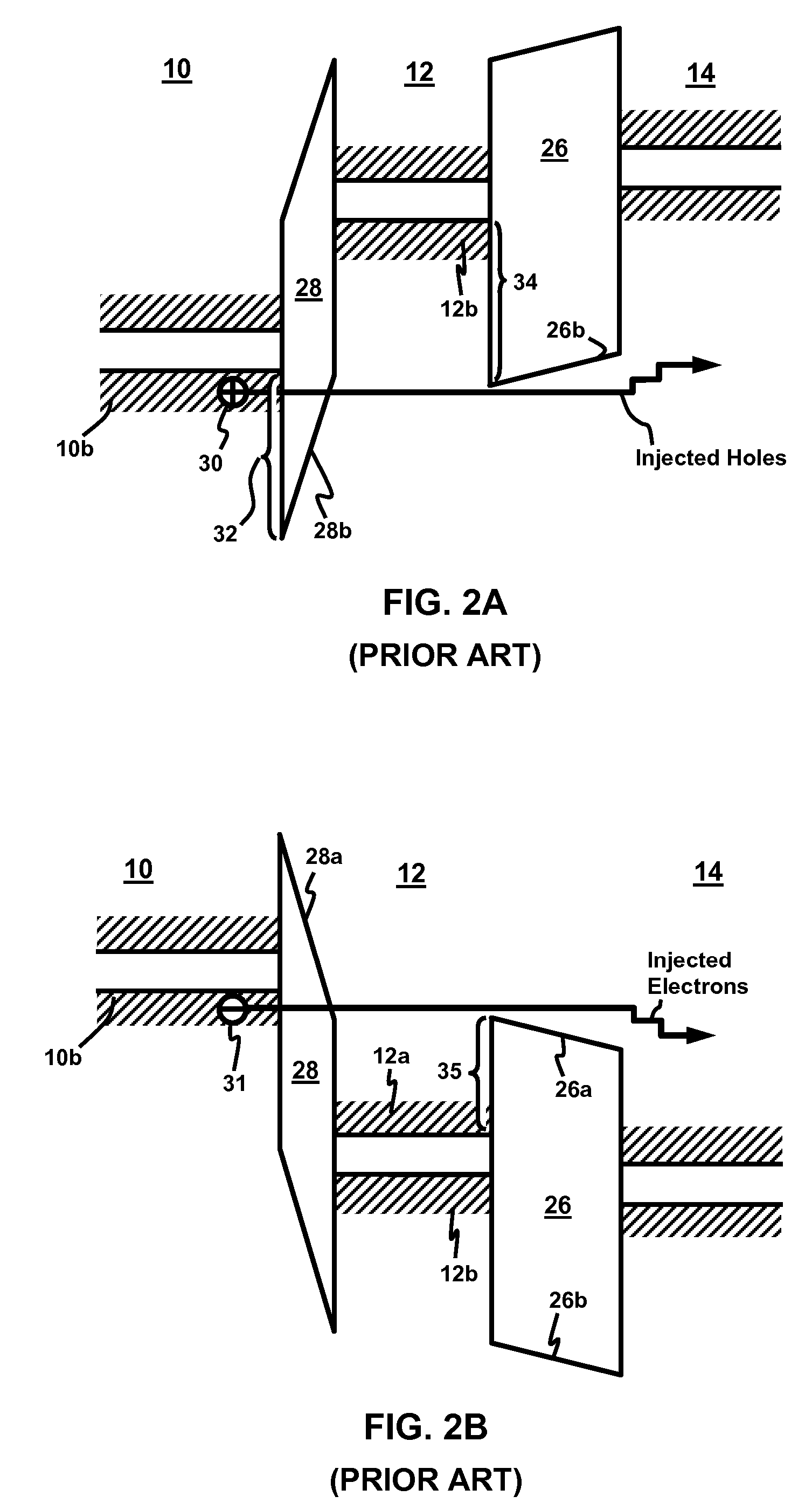
Parasitic holes backward injection problem is another major problem for the mechanism employed in prior art.
The problem on backward injected holes 38 is caused by the requirement on higher
work function in prior art.
Therefore, the symmetrical tunneling structure of prior art cannot be optimized to suppress parasitic charge carriers for both program and erase operations simultaneously.
This requirement results in larger
cell size, and limits the cell of prior art from practical application.
This problem also exists in operating the
amplifier by Mead, wherein
metal is employed as the material for base, which is equivalent to the ballistic gate 12 in FIG. 3B.
The backward injected holes can unduly increase the base current of the
amplifier, and hence degrade the performance of such device when used an
amplifier.
In addition to the problems described above, the injection mechanism and energy band structure employed in prior art also can suffered from
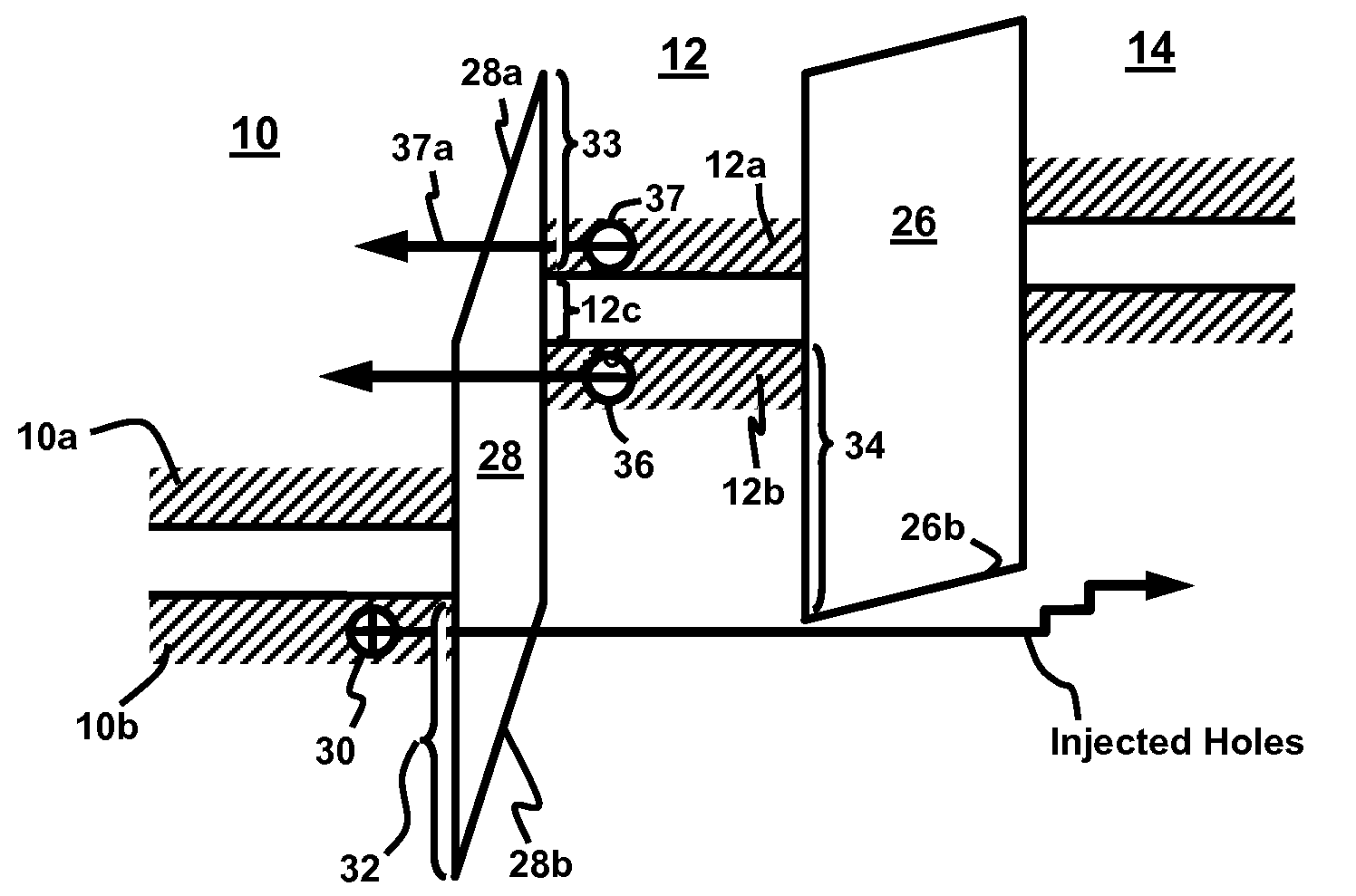
impact ionization problem. FIG. 3B shows the
impact ionization problem in the prior art band structure in FIG. 2B.
The holes 40a are highly energized and can be backward injected to gate 10 creating traps in
dielectric 28 as passing through, thus causing reliability problem.
These effects are uncontrollable, where current can unduly increase to result in current loading issue on supporting circuitry for memory operations.
The effects further cause reliability problem.
The
cell structure in prior art thus demands stringent control on the
threshold voltage, and is believed having low manufacturability yield and difficulties in practical applications.
The backward injected electrons 37 have energy high enough to impact ionize charge carriers in tunneling gate 10 to cause loading issue on supporting circuitry and reliability problem.
The injection mechanism, energy band and
cell structure in prior art thus face similar issues in both the program and the erase operations, and the memory is believed having low manufacturability yield and difficulties in practical applications.
The
cell structure in prior art thus demands stringent control on the
dielectric breakdown, and is believed having difficulties in practical applications.
Therefore, it results in a large
parasitic capacitance C between gates 10 and 12, and is undesirable as it introduces adverse impact on cell operation.
Therefore, the cell architecture in prior art further suffer from the compromise between suppressing the parasitic electrons and suppressing the total
capacitance of ballistic gate 12.
The needs on a thin thickness unavoidably results in a high
sheet resistance to that layer.
Therefore, prior art suffers from a much larger resistance R on both tunneling gate 10 and ballistic gate 12.
First, it can cause a large
signal delay due to the combining effects of the large R and the large C (i.e. the RC
delay).
This is particularly a main issue on cell operation as the RC
delay can limit the speed on accessing a
memory cell when embedded in a large
memory array.
However, due to the RC delay, voltages on un-selected cells can be different than the desired values, and hence cell disturb is more prone to happen.
Furthermore, the large R can combine with a large current I to result in a IR effect, which can cause a
voltage drop when passing a
voltage in a
signal line.
The effect prevents the
voltage on a designated
electrode of a
memory cell from reaching its desired level, and hence can adversely impact cell operation.
This results in weak voltage-dependence on the current-voltage relationship.
Therefore, unselected cells in prior art are prone to cell disturb issues in both program and erase operations.
Further, another major problem encountered by the
transistor is to do with the low
transfer ratio due to the low efficiency of the injection mechanism.
However, the efficiency typically still ranges from about 0.01 to about 0.4, and thus prevents the
transistor from practical applications.

