Hydrocarbon production system and method of use

a technology of hydrocarbon production system and production method, applied in the direction of wellbore/well accessories, fluid removal, insulation, etc., can solve the problems of inability to achieve continuous or more economical hydrocarbon production, blockages within subsurface production tubing and surface flow lines, sucker rods simply cannot fall at an acceptable fall rate, etc., to improve fluid flow shear effect, improve heat transfer effect, and reduce fluid purge pressure

Inactive Publication Date: 2007-01-18
UTTLEY DENNIS FRLIN
View PDF7 Cites 22 Cited by
  • Summary
  • Abstract
  • Description
  • Claims
  • Application Information

AI Technical Summary

Benefits of technology

[0032] A wellhead output gas valve may be added to close off the compressed gas and hydrocarbon fluid flow between the wellhead output and the surface flow line's input end, in order to build sufficient compressed gas pressure within the subsurface compressed gas feed tubing string, and upon opening the wellhead output gas valve, a hydrocarbon fluid column may be rapidly purged, at a considerable velocity, from and through the subsurface production tubing string, through the wellhead, surface flow line, and into the hydrocarbon storage tank. The method is advantageous when there is compressed gas loss due to bubble loss through the production tubing fluid column, or when difficult earthen particulates or r...

Problems solved by technology

Within some oil wells, subterranean hydrocarbon reservoir characteristics, hydrocarbon fluid characteristics, drilling problems or the well-bore design may present problems wherein continuous or more economical hydrocarbon production is difficult or not possible while employing current production systems including subsurface sucker rod driven plunger pumps, progressive cavity pumps or other types of subsurface production pumps.
If the hydrocarbon fluid contains considerable amounts of earthen particulates, the earthen particulates may accumulate and cause blockages within the subsurface production tubing and surface flow line.
When the accumulation of earthen particulates becomes too great, the sucker rods simply will not fall at an acceptable fall rate, through the column of hydrocarbon and earthen materials.
Production thereby fails, and well servicing is required.
The earthen particulates may also cause extreme abrasion of the sucker rods and production tubing and premature failure of each, which requires replacement of each.
Sucker rod and production tubing abrasion, mechanical wear and stress is greatly increased in oil wells that have deviations off the vertical line due to drilling problems, or in slant, whipstocked or horizontal well-bores.
These pumps inherit all the problems associated with sucker rod use, are quickly destroyed when the well-bore fluid is pumped off or the rotors and stators are often badly damaged when pumping rock fragments or pyrite balls or sand slugs.
They have a much shortened life when pumping considerable amounts of earthen particulates, especially water sand.
Within many oilsands production wells, seizure of the sucker rods by accumulations of earthen particulates packed within the subsurface production tubing string is a never ending problem that may occur daily.
The rubber stator component of the progressing cavity subsurface production pump is easily damaged by sand slugs, rock or coal fragments, pebbles, pyrite balls or the high ...

Method used


Image

  • Hydrocarbon production system and method of use
  • Hydrocarbon production system and method of use
  • Hydrocarbon production system and method of use

Examples


Embodiment Construction

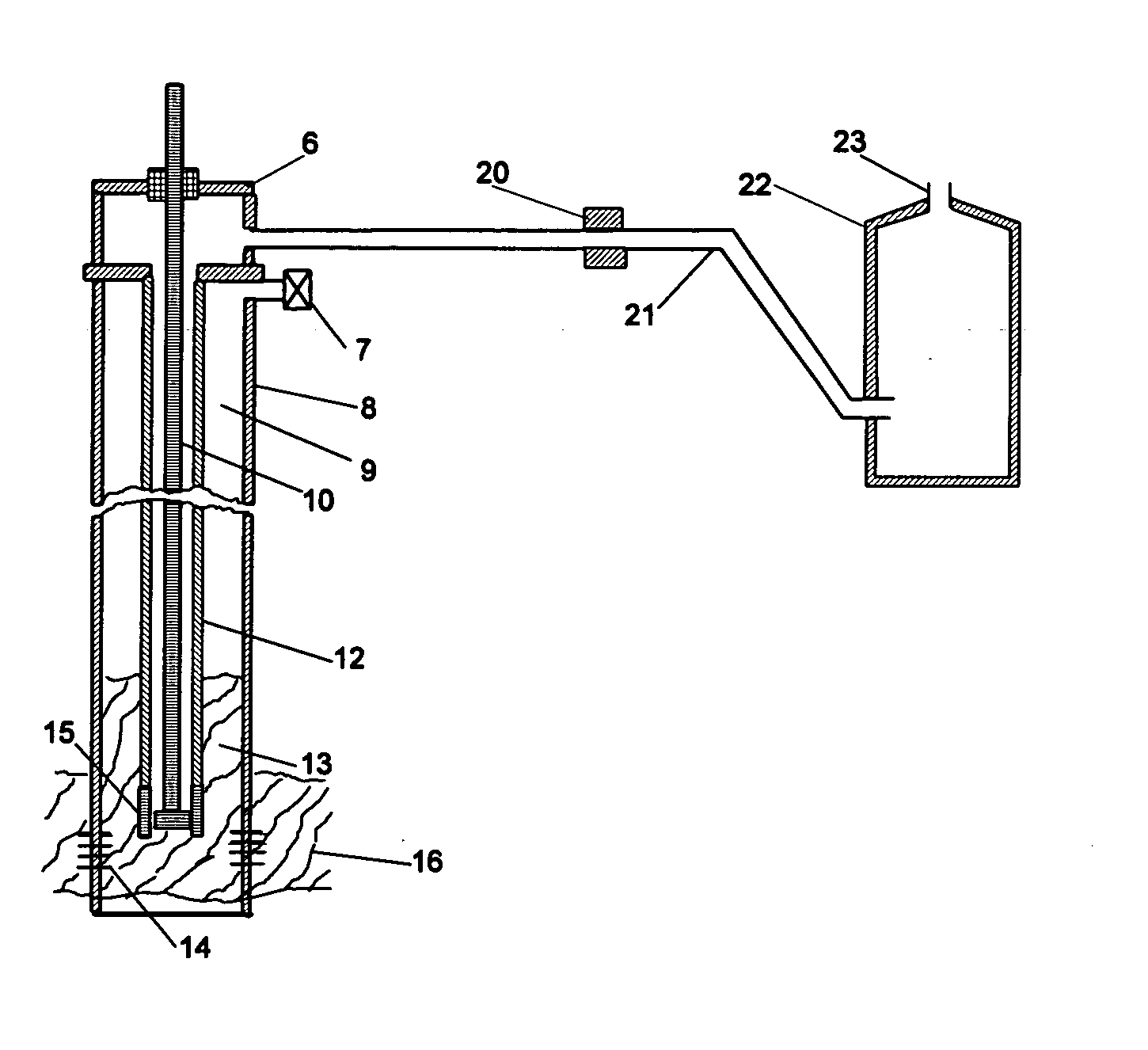
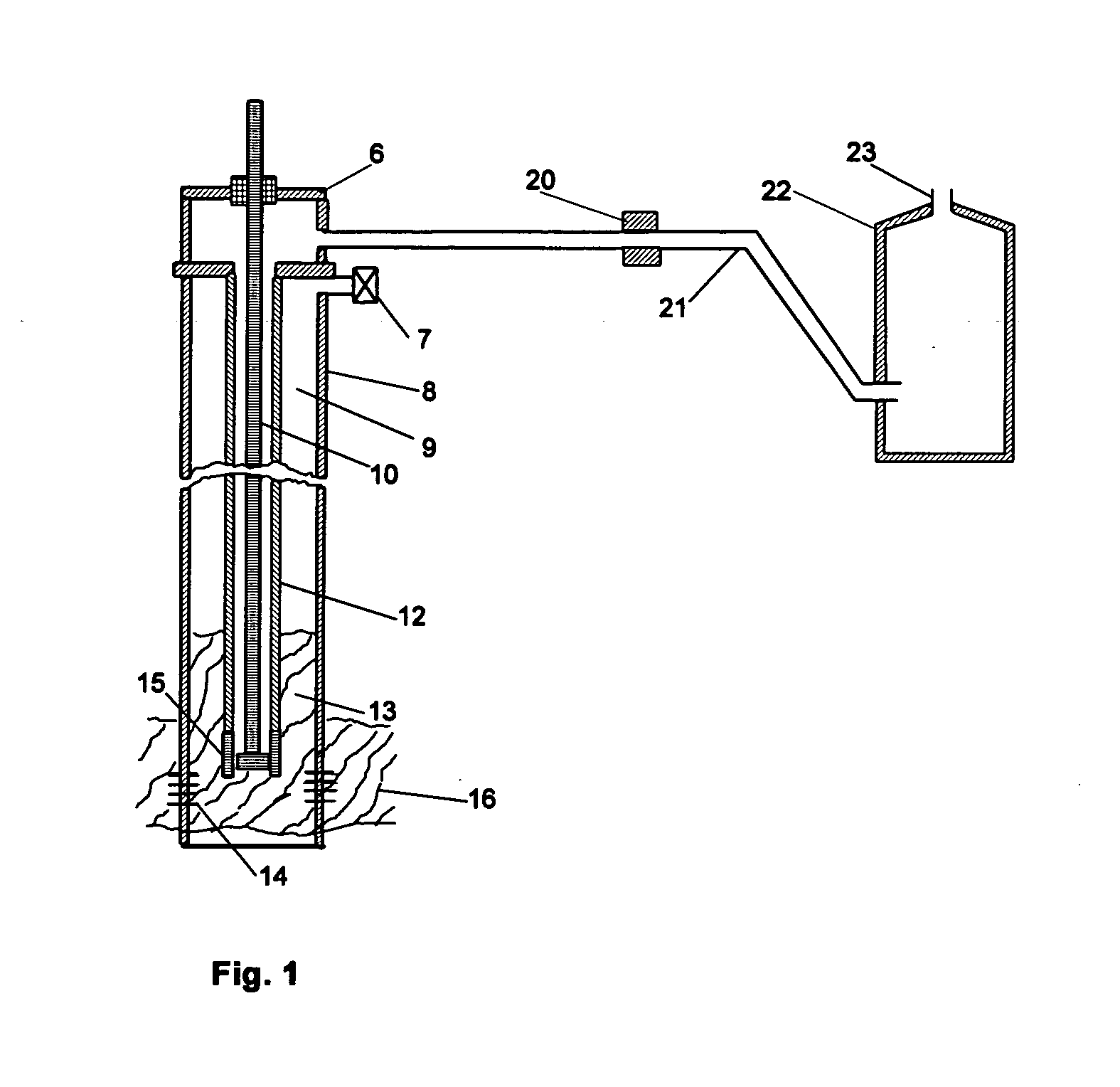
[0043] Referring initially to FIG. 1, a typical conventional oil well system includes a production casing indicated by reference numeral 8 which is placed into the earth. Within the casing 8 there is provided a subsurface production tubing string 12 which is basically a length or lengths of conduit coupled together from wellhead 6 to subsurface production pump 15. The system may also include what is commonly known as sucker rods 10. In use, hydrocarbon fluid 13 is fed by means of subterranean hydrocarbon reservoir 16 pressure into well-bore 9 through casing perforations 14 and pumped from well-bore 9 by subsurface production pump 15, into and through production tubing 12, into and through wellhead 6, into and through surface flow line 21, into and through optional surface check valve 20 and into hydrocarbon production fluid storage tank 22. Valve 7 is provided to vent casing gas. Optional surface check valve 20 is provided to prevent stored hydrocarbon fluid 13 from back-flowing fro...


PUM


Abstract

The method of the present invention provides a means to intake hydrocarbon fluid from a subsurface hydrocarbon reservoir, including any accompanying ground water or earthen contaminants, into the subsurface lower end of a tubing system. Compressed gas is then used to purge the hydrocarbon fluid and earthen contaminants from within the tubing system to a hydrocarbon production fluid storage tank or other handling facility at surface.

Description

BACKGROUND OF THE INVENTION [0001] 1. Field of the Invention [0002] The purpose of the method of the present invention is to provide an improved method and an improved apparatus to displace light, medium, heavy or viscose hydrocarbon fluid that may contain earthen contaminants from subterranean hydrocarbon reservoirs, to a hydrocarbon production fluid storage tank or other handling facilities on ground surface, by means of oil well production, wherein all currently used subsurface production pump systems are mechanically incapable of sustained or economic production. [0003] The method of the present invention provides a means to intake hydrocarbon fluid from a subsurface hydrocarbon reservoir, including any accompanying ground water or earthen contaminants, into the subsurface lower end of a tubing system. Compressed gas is then used to purge the hydrocarbon fluid and contaminants from within the tubing system to a hydrocarbon production fluid storage tank or other handling facility...

Claims


Application Information

Patent Timeline
IPC IPC(8): E21B43/24E21B43/00
CPCE21B43/122
Inventor UTTLEY, DENNIS F.
Owner UTTLEY DENNIS FRLIN
Why Eureka
Try Eureka