Ring oscillator with constant 50% duty cycle and ground-noise insensitive

Active Publication Date: 2007-01-18
DIALOG SEMICONDUCTOR
View PDF9 Cites 10 Cited by
  • Summary
  • Abstract
  • Description
  • Claims
  • Application Information

AI Technical Summary

Benefits of technology

[0015] In accordance with the objects of this invention a method to achieve ground noise insensitivity and a constant duty-cycle of chain ring oscillators over temperature and process variations has been achieved. The method comprises, first, the provision of a chain ring oscillator having n-stages and a clocked means to remove noise from clock pulses. The next steps of the method are to select the output of a stage of the ring oscillator wherein such a phase shift between said stage and the nth stage exists that a subtraction of both outputs eliminates any duty cycle variations due to process and temperature variations, to generate a signal being the result of a subtraction of the output of the stage selected in the previous step from the output of the nth stage, and to clock with the signal generated in the previous step a means to remove noise from clock pulses from the output of the nth stage of the ring oscillator. The last step is to buffer the signal, after noise has been removed in the previous step, to provide the final clock signal of the ring oscillator.
[0016] In accordance with the objects of this invention a chain ring oscillator to achieve a constant duty-cycle over temperature and process variations has been achieved. This chain ring oscillator comprises, first, n identical cascaded stages of inverters, a system current source generating a reference current, wherein a first terminal is connected to VDD voltage and a second terminal is connected to a means to generate two reference currents. Furthermore the ring oscillator comprises said means to generate two reference currents wherein a first reference current is provided to control each of said first current sources of each of said inverter stages and a second reference current is provided to control each of said second current sources of each of said inverter stages, and, being the key of the invention, a circuit to stabilize the duty cycle and to remove noise from the clock pu

Problems solved by technology

It is obvious that any noise from any source is spreading through the oscillator and that changes of the temperature impacts the electrical properties of the inverter stages and hence impacts frequency and duty cycles of the ring oscillator.
It is a challenge for the engineers to build

Method used


Image

  • Ring oscillator with constant 50% duty cycle and ground-noise insensitive
  • Ring oscillator with constant 50% duty cycle and ground-noise insensitive
  • Ring oscillator with constant 50% duty cycle and ground-noise insensitive

Examples


Embodiment Construction

[0026] The preferred embodiments disclose a CMOS on-chip chain ring oscillator having a constant duty-cycle over temperature and process variations.

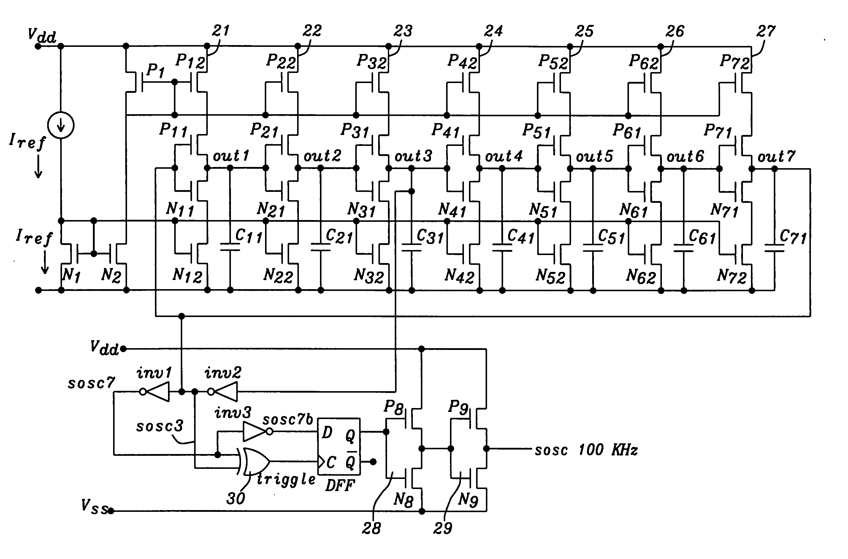
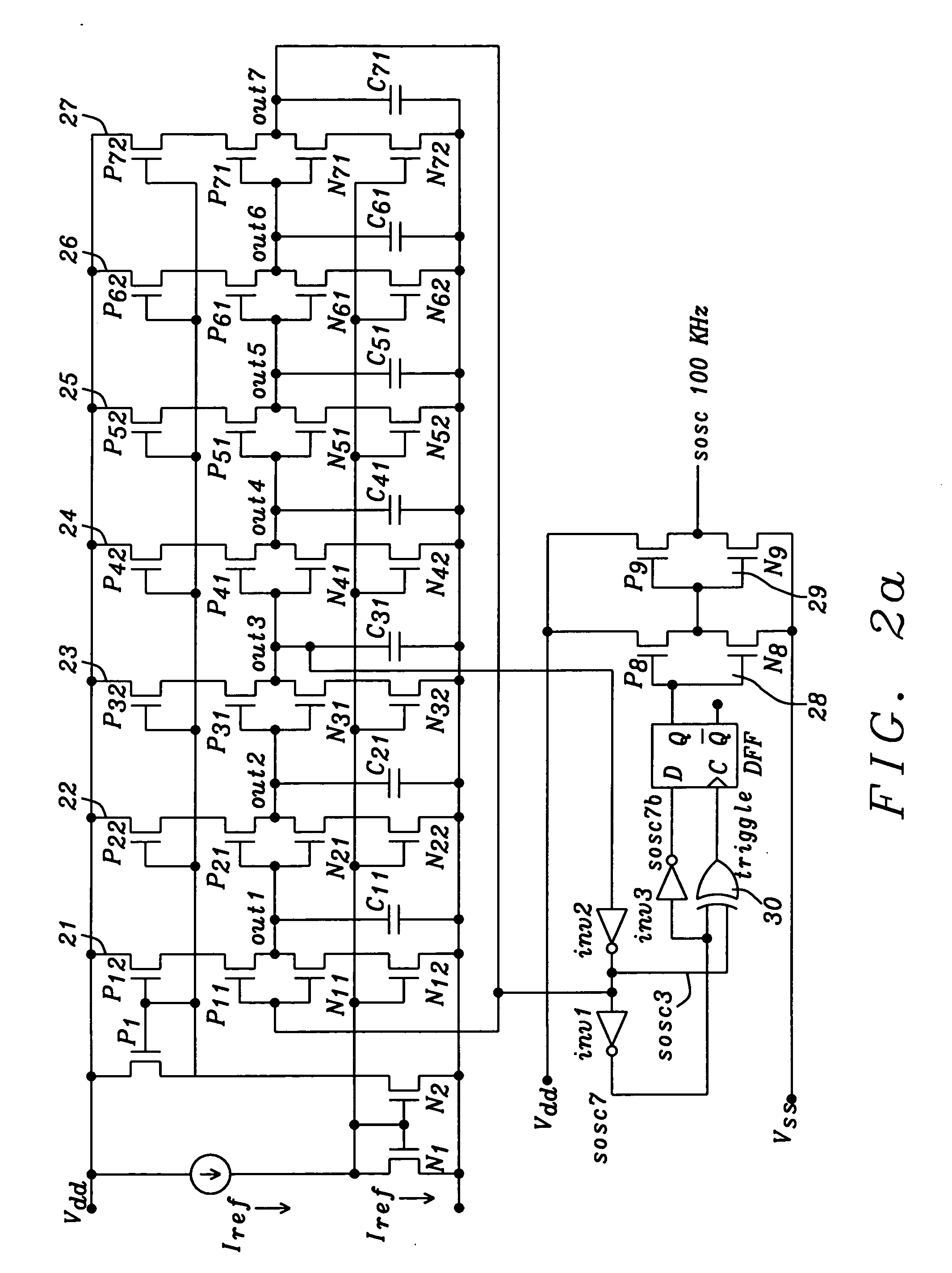
[0027]FIG. 2a shows a schematic of the circuit of a preferred embodiment of the present invention, a 100 KHz clock generator having a constant duty cycle of about 50%. This preferred embodiment is described in detail now.

[0028] This ring oscillator comprises seven identical stages 21-27. Each stage has about unity voltage gain gm and 360° / 7 phase shift.

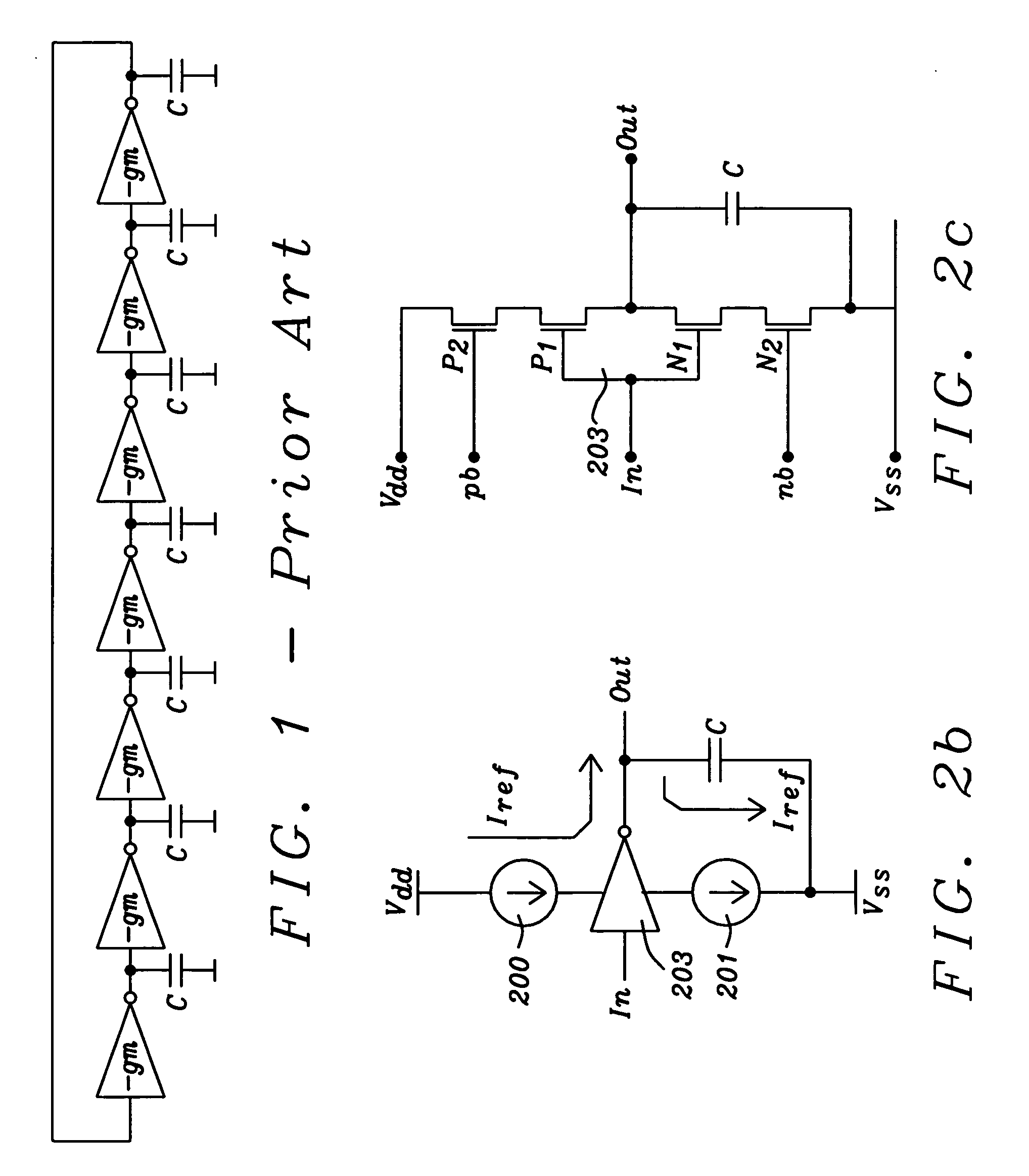
[0029]FIG. 2b shows the basic functional components of one of the identical stages and

[0030]FIG. 2c shows correspondent circuit components to the stage shown in FIG. 2b.

[0031] Writing the open-loop transfer function of the circuit shown in FIG. 2a we have H⁡(j*ω)=-gm*R1+j*ω*R*C=-gm*R1+j*7*ωω0;ω0=7R*C.

wherein R and C represent the output resistance and the load capacitance of one stage, respectively, and (gm*R) is the gain required for steady oscillations.

Writing the total open-loo...


PUM


Abstract

Methods and circuits for chain ring oscillators having a constant duty cycle and being insensitive to ground noise have been disclosed. The ring oscillator generates n outputs with 360°/n phase shift and each stage is delayed by T2×n.
The output of a suitable stage is selected so that a digital XOR-gate, using the output of a selected stage and the output of the nth stage, eliminates variations of the duty cycle caused by temperature and process variations. In case a 50% duty cycle is desired the stage number N of the selected stage can be calculated using the equation N=(n−1)/2. The duty cycle can be varied by selecting the output of another gate. A D-flipflop, clocked by the output of the XOR-gate removes noise from the clock pulses.

Description

BACKGROUND OF THE INVENTION [0001] (1) Field of the Invention [0002] This invention relates generally to ring oscillator circuits and relates more particularly to a CMOS on-chip chain ring oscillator being insensitive to ground noise and having a constant 50% duty cycle over temperature and process variations. [0003] (2) Description of the Prior Art [0004] Ring oscillators are used for a variety of purposes. Usually ring oscillators are used as an internally generated clocking source, or as a stage in a more complex system such as a voltage controlled oscillator (VCO) or a phase locked loop (PLL). [0005]FIG. 1 prior art shows a block diagram of a 7-stage CMOS inverter chain ring oscillator. Normally the number of stages is an odd number with the output of the cascade fed back to the input of the inverter chain. An oscillator provides an output at a specific frequency with no input signal required. The frequency of the oscillator shown at FIG. 1 prior art is completely dependent on t...

Claims


Application Information

Patent Timeline
IPC IPC(8): H03K3/03
CPCH03K3/017H03K3/0315
Inventor JI, CANG
Owner DIALOG SEMICONDUCTOR
Why Eureka
Try Eureka