Percutaneous heart valve

a heart valve and percutaneous technology, applied in the field of percutaneous heart valves, can solve the problems of the mitral regurgitation, and achieve satisfactory stability and so as to avoid affecting the function of the heart valv

Active Publication Date: 2007-01-18
THE TRUSTEES OF THE UNIV OF PENNSYLVANIA
View PDF80 Cites 1033 Cited by
  • Summary
  • Abstract
  • Description
  • Claims
  • Application Information

AI Technical Summary

Benefits of technology

[0016] guiding the folded heart valve beyond the distal end of the catheter so as to cause the heart valve to elastically unfold to a stable unfolded position;
[0021] The external force applied to adjust the claws is provided by manipulating at a proximal end of the catheter filaments that passes through the catheter and connect at a distal end to the claws. The filaments may also be used to switch the heart valve between its two stable configurations and to open the claws. The filaments are removed once implantation is completed or may be left in the heart valve prosthesis, drawn close to the body member of the heart valve prosthesis so as not to impede blood flow. Separate fixed length filaments attach one side of a claw to a leg of the body member so that when the longer filaments are pulled beyond a certain point the claws are opened further.
[0022] A significant benefit of such a method is that the steps of guiding the unfolded heart valve to the implantation position and adjusting the claws to hold the heart valve in place may be repeated until the position, stability and functioning of the heart valve are satisfactory. Also, by forming the heart valve from elastic materials, the heart valve may push outward on the heart tissue in the stable unfolded position so as to assist anchoring the heart valve in the heart tissue.

Problems solved by technology

Similarly, mitral regurgitation due to ischemic and degenerative (prolapse) disease has been shown to contribute to left ventricular dysfunction due to remodeling, and to left ventricular dilation, resulting in worsening of the mitral regurgitation.
Currently, malfunctioning heart valves are usually replaced with biologic or mechanical prostheses through open-heart surgery with the attendant significant risk of death, stroke, infection, bleeding, and complications due to the use of general anesthesia and cardiopulmonary bypass.
Such procedures also have significant potential for a long recovery period.
However, for certain disease states, percutaneous alternatives have been used in place of open-heart surgery due to the lower morbiaity and mortality.
Such a design is not amenable to placement of the heart valve prosthesis at the location of the biologic valve.
It is also difficult to position these designs as one has to inflate a balloon in a moving column of blood white the heart is beating and one only gets one chance to accurately deploy it.
An additional difficulty occurs when deploying a stented heart valve in an annulus that is not thickened by calcium.
However, when calcium is not present, as in other causes of aortic valve disease and in the mitral position, the stent may be difficult to anchor on the relatively thin annulus.
Furthermore, the nature by which the stent folds on a balloon and then expands with plastic deformability limits the ratio of its initial to final size such that it will, by necessity, have a fairly large profile making percutaneous insertion via catheter more difficult in a valve annulus with a large diameter that has not been reduced by calcium deposition.

Method used


Image

  • Percutaneous heart valve
  • Percutaneous heart valve
  • Percutaneous heart valve

Examples


Embodiment Construction

[0039] The invention will be described with reference to FIGS. 1-12. Those skilled in the art will appreciate that the description given herein with respect to these figures is for exemplary purposes only and is not intended in any way to limit the scope of the invention. All questions regarding the scope of the invention may be resolved by referring to the appended claims.

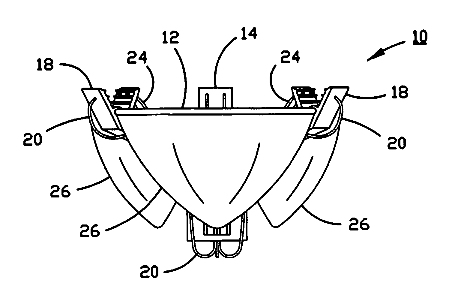
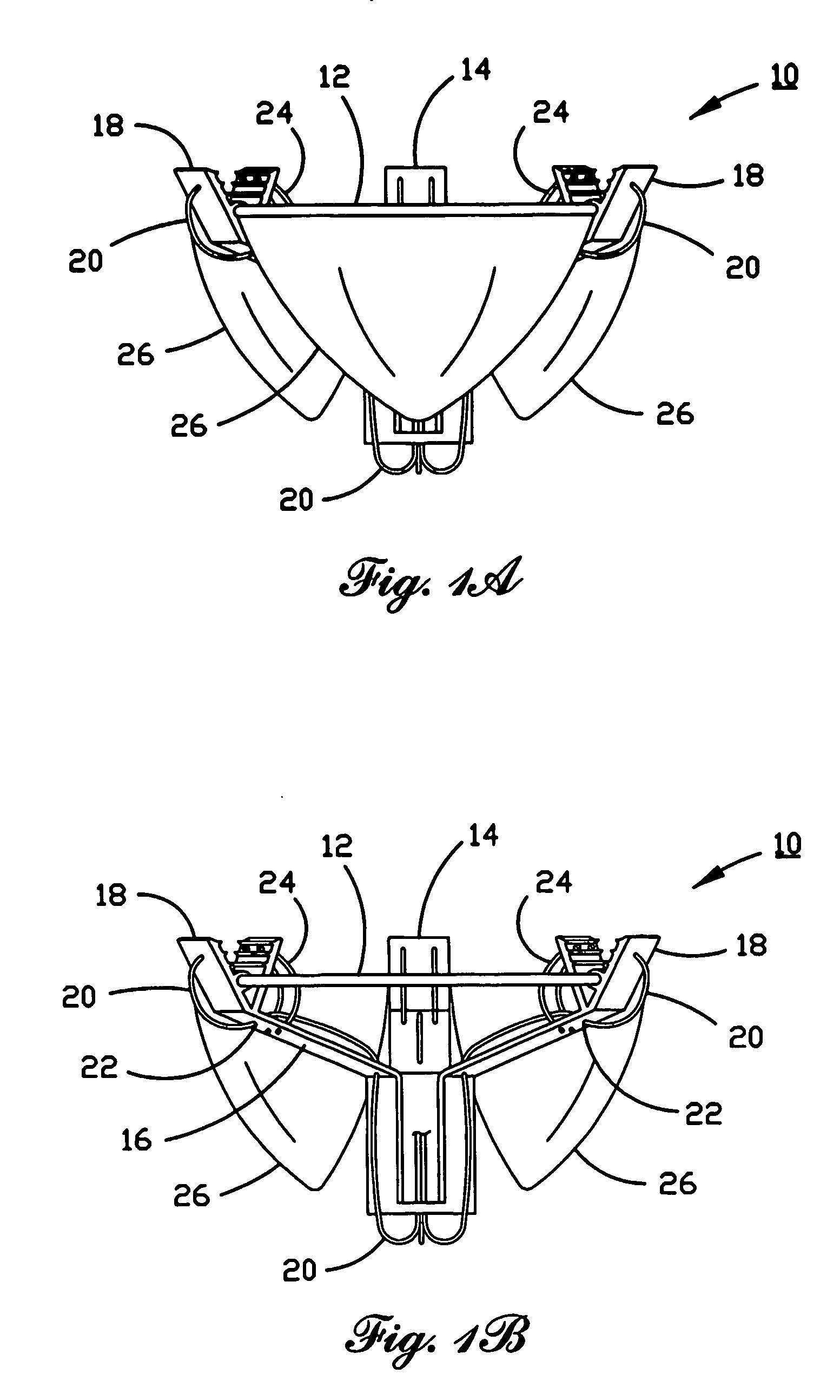
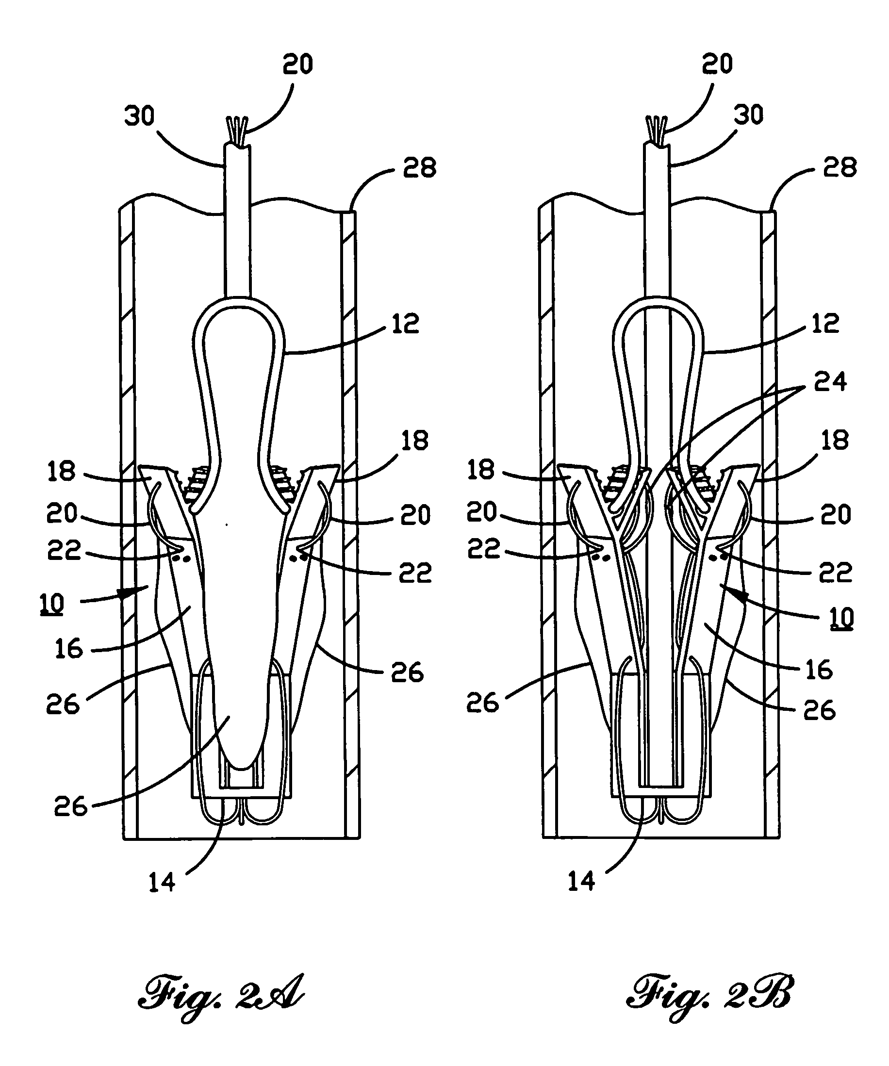
[0040] The heart valve described herein has a triangular-based bistable compliant structure that forms the housing for valve leaflets made of standard biologic or artificial prosthetic material, such as cryo or chemically preserved bovine pericardium. The structure is folded inside a catheter for transseptal delivery to the mitral valve cavity or by direct venous or arterial delivery to the aortic valve, pulmonary valve, or tricuspid valve cavities. The folded structure is advanced through the catheter by, for example, a smaller diameter guide catheter, to the implantation position (e.g., left atrium for mitral v...


PUM


Abstract

A percutaneously inserted bistable heart valve prosthesis is folded inside a catheter for transseptal delivery to the patient's heart for implantation. The heart valve has an annular ring, a body member having a plurality of legs, each leg connecting at one end to the annular ring, claws that are adjustable from a first position to a second position by application of external force so as to allow ingress of surrounding heart tissue into the claws in the second position, and leaflet membranes connected to the annular ring, the body member and / or the legs, the leaflet membranes having a first position for blocking blood flow therethrough and a second position for allowing blood flow therethrough. The heart valve is designed such that upon removal of the external force the claws elastically revert to the first position so as to grip the heart tissue positioned within the claws, thereby holding the heart valve in place. The body member and claws may be integrated into a one-piece design. The heart valve may be used as a prosthesis for the mitral valve, aortic valve, pulmonary valve, or tricuspid valve by adapting the annular ring to fit in a respective mitral, aortic, pulmonary, or tricuspid valve opening of the heart.

Description

CROSS-REFERENCE TO RELATED APPLICATIONS [0001] The present patent application claims priority to U.S. Provisional Patent Application Ser. No. 60 / 488,838, filed Jul. 21, 2003, the contents of which are hereby incorporated by reference in their entirety.FIELD OF THE INVENTION [0002] The present invention is directed to a design for a percutaneously inserted bistable heart valve prosthesis that may be folded inside a catheter for delivery to the mitral valve and other valves of the heart for implantation. BACKGROUND OF THE INVENTION [0003] Heart valve regurgitation occurs when the heart valve does not close completely as a result of disease or injury. Pulmonary valve regurgitation has been shown to increase a patient's susceptibility to arrhythmias, sudden death and right ventricular dysfunction. Similarly, mitral regurgitation due to ischemic and degenerative (prolapse) disease has been shown to contribute to left ventricular dysfunction due to remodeling, and to left ventricular dila...

Claims


Application Information

Patent Timeline
Patent Type & Authority Applications(United States)
IPC IPC(8): A61F2/24A61F
CPCA61F2/243A61F2/2412Y10S623/904
Inventor HERRMANN, HOWARD C.MANKAME, NILESHANANTHASURESH, SURESH
Owner THE TRUSTEES OF THE UNIV OF PENNSYLVANIA
Why Eureka
Try Eureka