
Device and method for large area lithography

a large area, lithography technology, applied in the field of large area lithography, can solve the problems of inability to handle large area substrate surfaces in a single imprint step, limited photolithography by diffraction, and difficult imprint process for larger surface areas, so as to improve the fabrication of structures

Active Publication Date: 2007-01-25
OBDUCAT AB SE
View PDF29 Cites 34 Cited by
  • Summary
  • Abstract
  • Description
  • Claims
  • Application Information

AI Technical Summary

Benefits of technology

"The present invention provides methods and apparatus for improving the fabrication of structures with three-dimensional features on a micro or nanometer scale. Specifically, the invention provides methods for transferring a pattern from a template to a substrate using a flexible membrane and an overpressure to a medium present on the membrane. The invention also provides methods for exposing the substrate to radiation for solidifying the pattern. The invention can be used with various radiation sources, such as air-cooled or pulsating radiation. The invention can be applied to a variety of substrates, such as glass or liquid. The technical effects of the invention include improved pattern transfer accuracy and efficiency, as well as larger pattern sizes and more precise pattern shapes."

Problems solved by technology

For fine scale replication, photolithography is limited by diffraction, which is dependent on the wavelength of the radiation used.
The larger the area to be imprinted, the larger the actual expansion and contraction, which can make the imprint process more difficult for larger surface areas.
Such a system is, however, not capable of handling large area substrate surfaces in a single imprint step.
This technique is therefore very time-consuming, and less than optimum for large scale production.
Furthermore, besides problems of repeated alignment errors, and high accuracy demands on the translation stage, this technique suffers from the drawback that continuous structures which are larger than said template size cannot be produced.
All in all, this means the productions costs may be too high to make this technique interesting for large scale production of fine structure devices.

Method used


Image

  • Device and method for large area lithography
  • Device and method for large area lithography
  • Device and method for large area lithography

Examples


Embodiment Construction

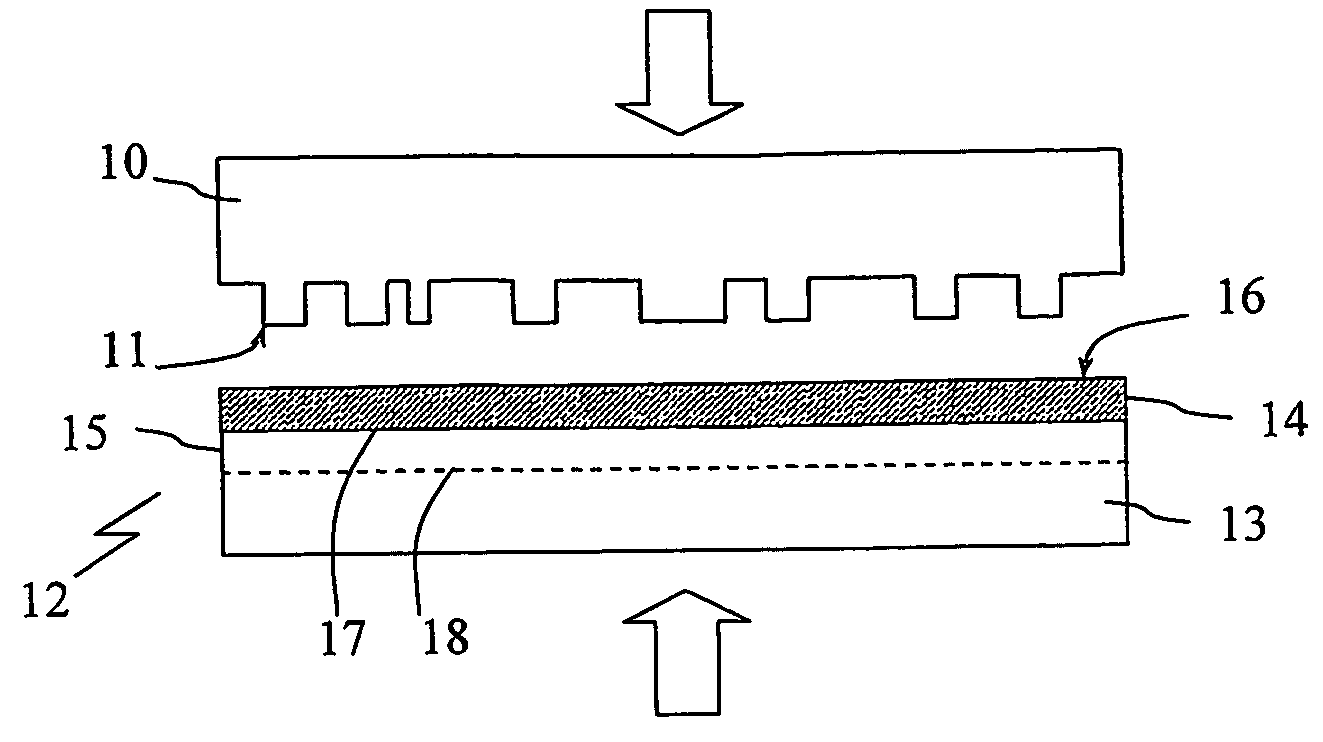
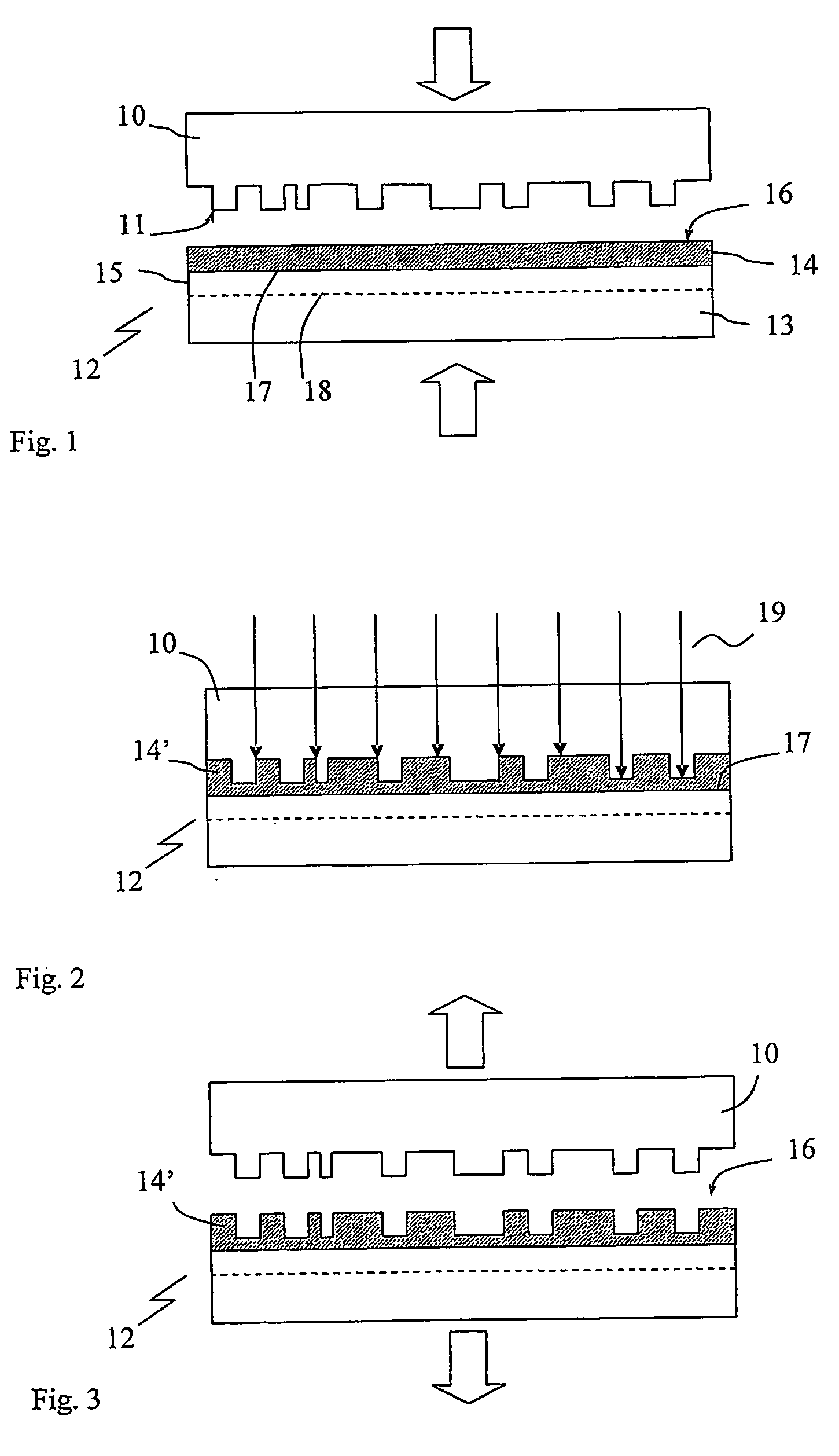
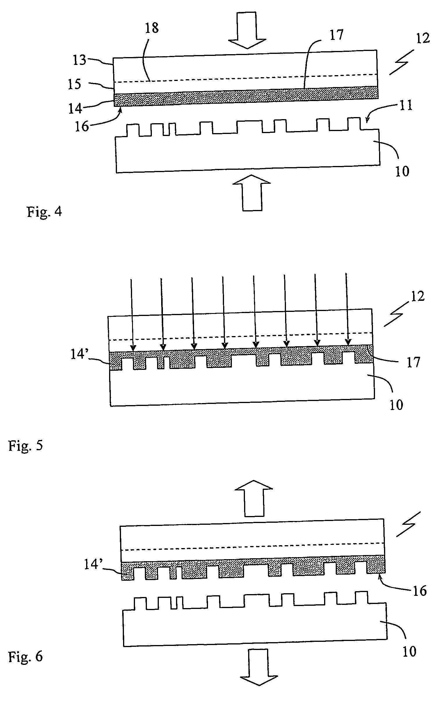
[0055] The present invention relates, in general, to a method of transferring a pattern from a template to a substrate, by creating a relief image of a structure on a surface of the template on a surface of the substrate. The surface of the template and the surface of the substrate are in this process arranged generally parallel to each other, and the transfer of the pattern is obtained by pressing the structured template surface into a formable layer disposed on the substrate surface. The formable layer is treated to solidify, such that its shape is forced to resemble the template surface. The template can thereafter be removed from the substrate and its layer, said layer now being an inverted topographical replica of the template. In order to permanent the transferred pattern in the substrate, further processing may be required. Typically, wet or dry etching is performed to selectively etch the surface of the substrate under the solidified layer, whereby the pattern in the solidif...


PUM

PropertyMeasurementUnit
pressureaaaaaaaaaa
wavelength rangeaaaaaaaaaa
widthaaaaaaaaaa

Abstract

Apparatus and method for transferring a pattern from a template (10) having a structured surface to a substrate (12) carrying a surface layer of a radiation polymerisable fluid (14). The apparatus comprises a first main part (101) and a second main part (102) having opposing surfaces (104; 105), means for adjusting a spacing (115) between said main parts, support means (106) for supporting said template and substrate in mutual parallel engagement in said spacing with said structured surface facing said surface layer, a radiation source (110) devised to emit radiation into said spacing. A cavity (115) has a first wall comprising a flexible membrane (113) devised to engage said template or substrate, and means (114; 116) are provided for applying an adjustable overpressure to a medium present in said cavity, whereby an even distribution of force is obtained over the whole of the contact surface between the substrate and the template.

Description

FIELD OF THE INVENTION [0001] The invention relates to a device in connection with the lithography of structures on a micro or nanometre scale. In particular, the invention relates to imprint lithography on large area substrates or objects. BACKGROUND [0002] The trend in microelectronics, as well as in micromechanics, is towards ever smaller dimensions. Some of the most interesting techniques for fabrication of micro and submicro structures include different types of lithography. [0003] Photolithography typically involves the steps of coating a substrate with a photoresist material to form a resist layer on a surface of the substrate. The resist layer is then exposed to radiation at selective portions, preferably by using a mask. Subsequent developing steps remove portions of the resist, thereby forming a pattern in the resist corresponding to the mask. The removal of resist portions exposes the substrate surface, which may be processed by e.g. etching, doping, or metallisation. For...

Claims


Application Information

Patent Timeline
Patent Type & Authority Applications(United States)
IPC IPC(8): B29C35/08B29C45/12B29C43/10G03F7/00G03F7/20H05K3/00H05K3/10
CPCB82Y10/00B82Y40/00G03F7/0002G03F7/2012H05K2203/0108H05K3/0023H05K3/107H05K2201/0108H05K3/0014
Inventor HEIDARI, BABAKBECK, MARC
Owner OBDUCAT AB SE
Learn More