Light source device with equalized colors split, and method of making same

a technology of light source and equalization color, which is applied in the direction of light source semiconductor devices, lighting and heating apparatus, display means, etc., can solve the problems of color split, poor light diffusion, and inability to improve around the periphery of illumination, and achieve high luminous efficiency

Active Publication Date: 2007-01-25
TOYODA GOSEI CO LTD
View PDF23 Cites 80 Cited by
  • Summary
  • Abstract
  • Description
  • Claims
  • Application Information

AI Technical Summary

Benefits of technology

[0006] An exemplary feature of the invention is to overcome the above-mentioned limitations. A light source device according to the present invention has a well-equalized illumination with a high luminous efficiency.

Problems solved by technology

Because the amount of the fluorescent substance is not enough for diffusing when the white LED emits white illumination, a good light diffusion cannot be expected.
Furthermore, when the light from the LED device is converged by a lens, a color split will occur because of an aberration of the lens.
The combined lens can improve the color split around the center of an illumination, but cannot improve it around the periphery of the illumination.
In this case, however, the lens cannot converge the light from the LED well.

Method used


Image

  • Light source device with equalized colors split, and method of making same
  • Light source device with equalized colors split, and method of making same
  • Light source device with equalized colors split, and method of making same

Examples


first embodiment

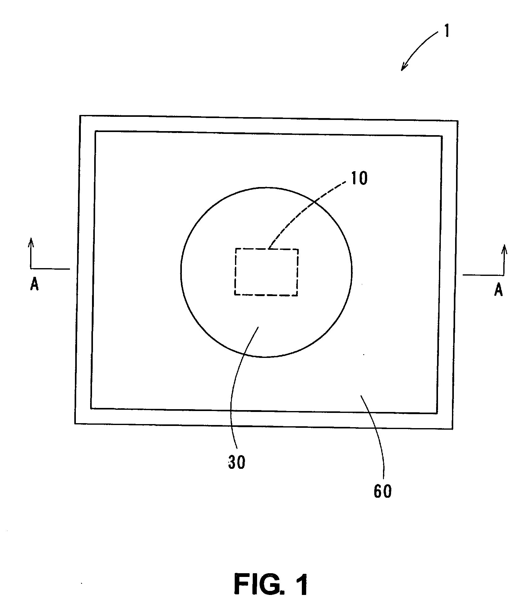
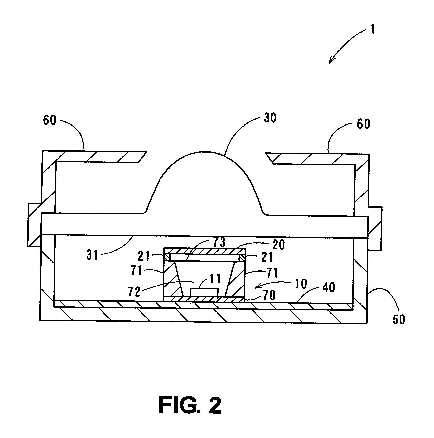
[0037] Referring to FIG. 1 and FIG. 2, the light source device 1 includes a surface mounted type light emitting diode device 10 (hereinafter referred to as LED device), a lens 30, a circuit board 40, a housing 50 and a cover 60. The LED device 10 includes an LED chip 11, a substrate 70, a reflector 71 and a sealing member 72 ( see FIG. 2). The LED device 10 also includes a Zener diode (not shown) for anti-electrostatic protection.

[0038] As shown in FIG. 3, the LED chip 11 includes a sapphire substrate 12 and a plurality of layers formed on the sapphire substrate 12. It has a main emission peak wavelength of around 470 nm. The LED chip 11 includes following layers: a p-type layer 16 is a p-GaN: Mg layer; a layer 15 includes InGaN layers that includes light emitting layers; an n-type layer 14 is an n-GaN:Si layer; a buffer layer 13 is an AlN layer; and substrate 12 is a sapphire substrate.

[0039] The n-type layer 14 of GaN with n-type impurity Si doped is grown through the buffer lay...

second exemplary embodiment

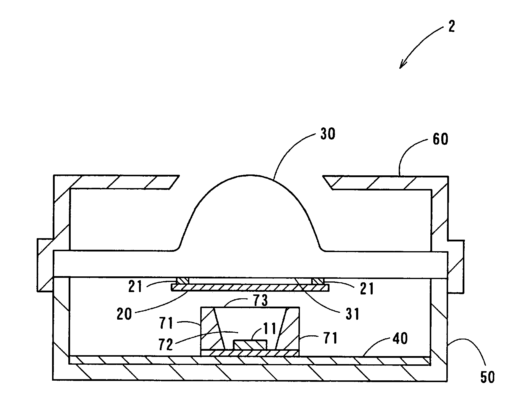
[0061] An explanation for the same parts and elements as the above mentioned embodiment is abbreviated. As shown in FIG. 4, the diffusing sheet 20 of a light source device 2 is fixed to the lens 30. In detail, the periphery of the diffusing sheet 20 is adhered to the light receiving face 31 of the lens 30 by the adhesive agent 21. Thus, the diffusing sheet 20 covers a center part of the light receiving face 31 of the lens 30 through an air layer. In the present exemplary embodiment, the adhesive agent is made of acrylic emulsion and a thickness of the adhesive agent 21 is about 0.1 mm.

[0062] A light from the LED device 10 of the light source device 2, as well as the light source device 1, is diffused at the diffusing sheet 20 and then enters the lens 30. As a result, a well-equalized and directed light is emitted from the lens 30. Also, a color split at a periphery can be reduced around a periphery of an illumination area.

[0063] The diffusing sheet 20 of the light source device 2 ...

third exemplary embodiment

[0065] An explanation for the same parts and elements as the above mentioned exemplary embodiments is abbreviated. As shown in FIGS. 5A through 5D, a light source device 3 includes a lens 80, a cover 81, a chip element (a substrate 84 and mounted parts) and a heat sink 82. The lens 80 may be made of poly carbonate, which is transparent material. As shown in FIGS. 6A and 6B, the lens 80 includes a convex lens at an upper side and a pair of engaging legs 80b, which are formed for fixing and positioning, at a lower side. A periphery of a diffusing sheet 87 is adhered to a light receiving face 80a of the lens 80. LIGHT UP 100 PBU (product name, KIMOTO Co., Ltd.) is used for the diffusing sheet 87.

[0066] The cover 81 may be made of poly butylene terephthalate (PBT) resin and includes an opening 81a for the lens 80. The cover 81 also includes engaging claws 81b at a side for fixing the cover 81 to the light source device 3. The substrate 84 is a heat radiation substrate and made of Alumi...


PUM


Abstract

A light source device includes a light emitting diode (LED) device, a lens and a light diffusing layer. The LED device includes an LED chip, which emits light, and a fluorescent, which converts a part of the light from the LED chip. The lens is located on a side of a light emitting face of the LED device. The light diffusing layer is located between the LED device and the lens. An air layer exists between the light diffusing layer and the LED device or between the light diffusing layer and the lens.

Description

CROSS REFERENCE TO RELATED APPLICATION [0001] This application is based upon, claims the benefit of priority of, and incorporates by reference Japanese Patent Application No. 2005-214664, which was filed on Jul. 25, 2005, and No. 2006-121783, which was filed on Apr. 26, 2006. BACKGROUND OF THE INVENTION [0002] The present invention relates to a light source device that includes a light emitting diode (LED) as a light source. The present invention specifically relates to the light source device that includes a LED chip with a fluorescent substance (e.g., a phosphor). [0003] In case that an illumination device for a specific area is needed, an LED device, which converges a light from the LED with a lens, is used as a spot light. Meanwhile, an LED device, which emits white illumination, is recently developed and put to practical use. [0004] A typical white LED includes a blue LED chip and a fluorescent substance that converts a part of a blue light from the blue LED chip and emits yell...

Claims


Application Information

Patent Timeline
Patent Type & Authority Applications(United States)
IPC IPC(8): F21V9/00F21V5/04F21V9/08H01L33/50H01L33/56H01L33/58H01L33/60
CPCF21K9/00H01L33/58F21Y2101/02F21V5/04F21K9/69F21Y2115/10Y10S362/80
Inventor NAWASHIRO, MITSUHIROINAGAKI, SATOSHI
Owner TOYODA GOSEI CO LTD
Why Eureka
Try Eureka