Method and apparatus of electromagnetic measurement

a technology of electromagnetic measurement and method, applied in the direction of resistance/reactance/impedence, instruments, measurement devices, etc., can solve the problems of inability to perform high-accuracy measurement, high accuracy, and high cost, and achieve high accuracy, convenient measurement, and smooth measurement

Inactive Publication Date: 2007-02-01
PANASONIC CORP
View PDF2 Cites 60 Cited by
  • Summary
  • Abstract
  • Description
  • Claims
  • Application Information

AI Technical Summary

Benefits of technology

[0041] When a switching part selects a through path, there are no generated an electric field and a magnetic field by flow of currents in an amplifier and electromagnetic caused by these fields, and also, there is no generated an electric field by application of voltage. Thus, measurement can be smoothly performed.
[0042] When electromagnetic emission from a device under test is measured while an electromagnetic field sensor moves in a measurement plane near the device under test, specification data of the device under test serving as a decision factor of an electromagnetic field intensity or structure information of the device under test for calculating a distance between a measurement point in the device under test and the electromagnetic field sensor is utilized as design data of the device under test. Thus,

Problems solved by technology

Consequently, the measurement requires expert knowledge, and takes much time.
However, since an electromagnetic intensity to be received is lowered and a resolution for measurement is also lowered, measurement with high accuracy cannot be performed.
This results in prolonged time for measurement and increased cost for a product.
Moreover, an electromagnetic measurement apparatus does not receive radiation from a device under test, but receives extraneous noise from a farfield.
This results in increased cost for measurement, that is, increased cost for a product.
If a conventional electromagnetic measurement apparatus estimates a current source which is a source of unnecessary radiation

Method used


Image

  • Method and apparatus of electromagnetic measurement
  • Method and apparatus of electromagnetic measurement
  • Method and apparatus of electromagnetic measurement

Examples


first embodiment

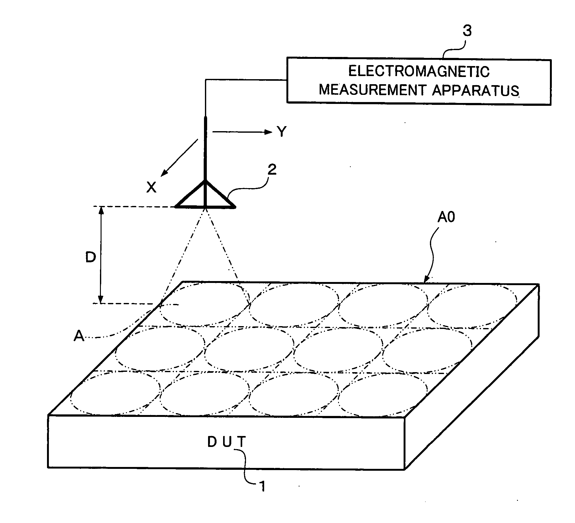
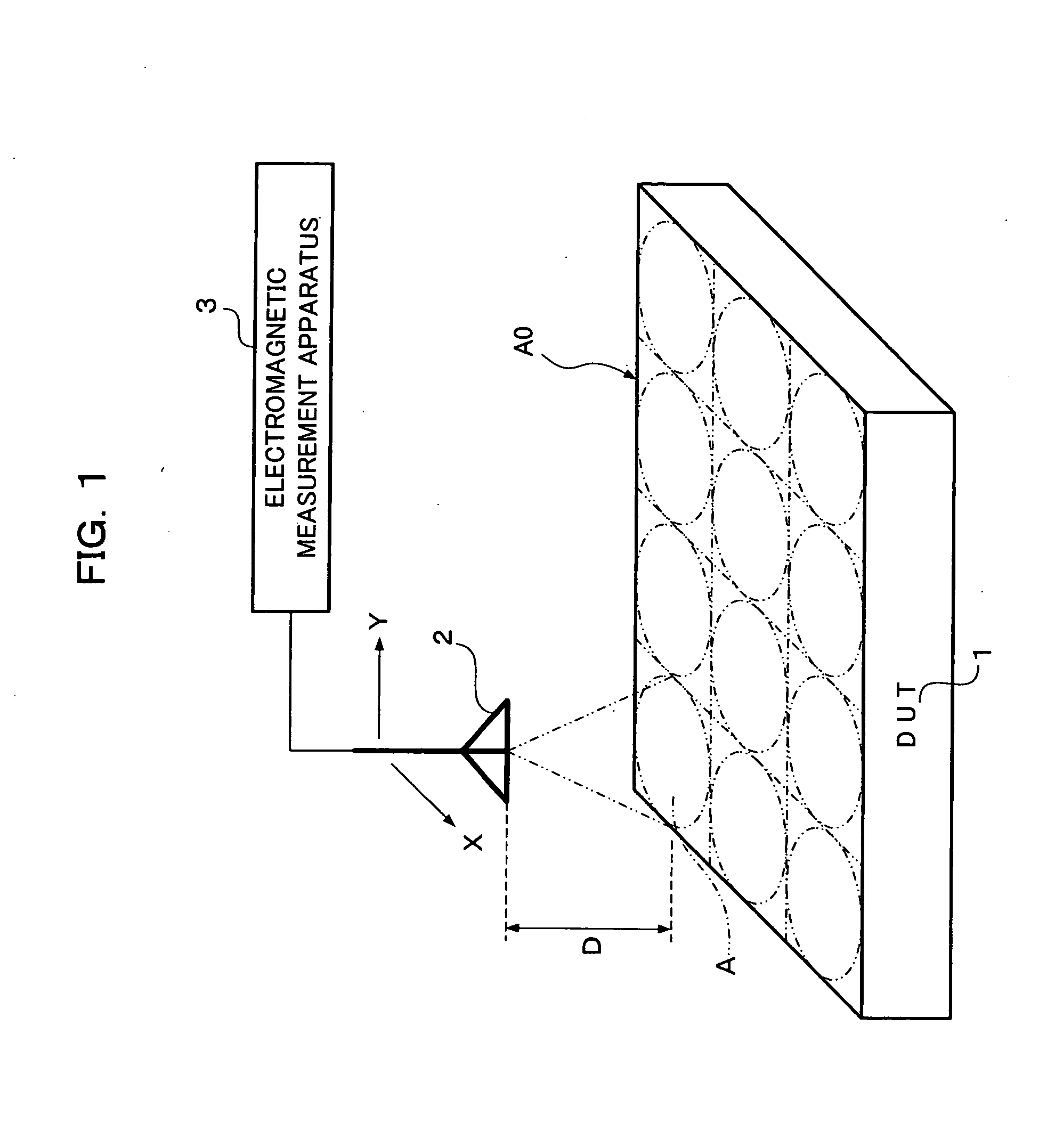
[0065]FIG. 1 illustrates an example of an electromagnetic measurement method according to a first embodiment of the present invention. As illustrated in FIG. 1, a probe 2 serving as an electromagnetic field sensor receives electromagnetic interference from a device under test (hereinafter, referred to as “DUT”) 1 generating electromagnetic waves, such as an electronic device. And an electromagnetic measurement apparatus 3 measures the electromagnetic interference. It is sufficient that the probe 2 receives electromagnetic interference or radio waves exerting adverse influences on peripheral devices and human bodies. The probe 2 used herein has directivity that a received band is widened in accordance with a measurement distance. Examples of the probe 2 include a loop antenna and an infinitesimal dipole antenna. However, the probe 2 is not limited to these examples.

[0066] Measurement is mainly performed within an electromagnetic near range (in general, radian sphere=wavelength / 2π ra...

second embodiment

[0097] FIGS. 10 to 15B show and illustrate a second embodiment of the present invention.

[0098]FIG. 10 illustrates an electromagnetic measurement apparatus 3 according to the second embodiment of the present invention. The electromagnetic measurement apparatus 3 allows an electromagnetic field sensor to move within a measurement plane spaced away from a DUT, which is formed based on design data, by a predetermined distance to measure an intensity of an electromagnetic field at each coordinate point in the measurement plane.

[0099] The electromagnetic measurement apparatus 3 includes a probe 2, a wide-band receiver 4, a controller 6A, a display 7 and a calculation processor 8. The probe 2 is an electromagnetic field sensor for receiving electromagnetic from a DUT 1.

[0100] The wide-band receiver 4 is a reception processing part having an amplifier, a mixer and the like and performing reception processing on the electromagnetic transmitted from the probe 2.

[0101] The controller 6A pe...

third embodiment

[0125] In the second embodiment, a flow of currents in a device under test is visualized by a current value at each coordinate point in a measurement plane estimated with high accuracy; thus, an electromagnetic source is evaluated. In a third embodiment, a probe 2 is allowed to move in an XY plane 18 near a DUT 1 such as an electronic device to receive electromagnetic, and a calculation processor 8 evaluates an electromagnetic field intensity of the electromagnetic from the DUT 1 at a high speed; thus, a source (a defective site to which countermeasures are made) of electromagnetic (noise) is correctly grasped at a low cost and some countermeasures are made to the source.

[0126] In this case, measurement distances dij are different from each other depending on respective measurement points Pij. Therefore, received electromagnetic field intensities cannot be evaluated based on a single standard.

[0127] Also in this case, as in the second embodiment, the calculation processor 8 utiliz...


PUM


Abstract

In order to direct a probe having directivity that a received band is widened in accordance with a measurement distance, toward a DUT, shift the received band of the probe in sequence, receive electromagnetic, and measure electromagnetic interference, a plurality of long and short measurement distances between the probe and the DUT are set, and measurement at the long measurement distance and measurement at the short measurement distance are performed plural times. Herein, the measurement at the short measurement distance is performed on a received band where electromagnetic interference is measured by the measurement at the long measurement distance. Thus, measurement of electromagnetic interference can be performed with high accuracy in a short time.

Description

BACKGROUND OF THE INVENTION [0001] 1. Field of the Invention [0002] The present invention relates to a method and an apparatus of electromagnetic measurement. More specifically, the present invention relates to a method and an apparatus of electromagnetic measurement, for measuring electromagnetic waves emitted from an electronic device, constituent elements thereof and peripheral devices thereof, mainly, electromagnetic interference in an electromagnetic near field. [0003] 2. Description of the Related Art [0004] In order to prevent that unnecessary radiation from an electronic device interferes with another device and exerts harmful influences on a human body, recently, regulations are established in many countries. At overseas, for example, there are established standards by FCC (Federal Communications Commission), CISPR (Comittie International Special des Perturbations Radioelectrique), VDE (Verband Deutscher Elektrotechniker) and the like. Also in Japan, there is established vo...

Claims


Application Information

Patent Timeline
IPC IPC(8): G01R31/302
CPCG01R31/001
Inventor KOSAKA, HIROFUMIIKEDA, KAZUHIKOKAJIWARA, SHOICHITANI, HIROYUKIUEDA, YOICHIROYAMAMOTO, ATSUSHI
Owner PANASONIC CORP
Why Eureka
Try Eureka