Cytometer on a chip

a chip and cytometer technology, applied in the field of cytometers, can solve the problems of complex experimental protocols that may be difficult to implement, complex compensation, and limited application of flow cytometry, and achieve the effect of high multiplexing and label-free manner and high parallel detection

Active Publication Date: 2007-02-01
CIENCIA
View PDF7 Cites 15 Cited by
  • Summary
  • Abstract
  • Description
  • Claims
  • Application Information

AI Technical Summary

Benefits of technology

[0010] In addition to spatially sorting cells based on cell phenotype, another objective is to measure cellular responses in real time or near real time without the use of molecular labels. Cells respond to environmental stimuli in a variety of ways (e.g., altering shape, secreting bioproducts, such as cytokines, lysing, undergoing programmed cell death, etc). The disclosed embodiments provide for detection of cellular responses to stimuli by including on the biosensor surface sets of secondary ROIs containing capture ligands to specific cell bioproducts. These “response ROIs” (to be distinguished from cell ROIs) are strategically placed in close proximity to and in predetermined spatial patterns relative to cell ROIs and may overlap the cell ROIs. The shape, location and pattern of cell ROIs and response ROIs are designed to generate spatial and temporal optical signatures which provide information on cell phenotype and function (e.g., secretion of cytokines), in near real time in a highly multiplexe

Problems solved by technology

Flow cytometry has a number of limitations.
One drawback is that flow cytometry requires pre-labeling of the cells with fluorescent antibodies or other fluorophores and entails complex experimental protocols that may be difficult to implement in many environments (e.g., resource-poor settings).
Disturbances in the sample stream can alter the information produced by a flow cytometer, making this technology

Method used


Image

  • Cytometer on a chip
  • Cytometer on a chip
  • Cytometer on a chip

Examples


Embodiment Construction

[0023] The following examples are given to illustrate various embodiments and aspects of the invention and are not intended to limit the claims in any manner whatsoever.

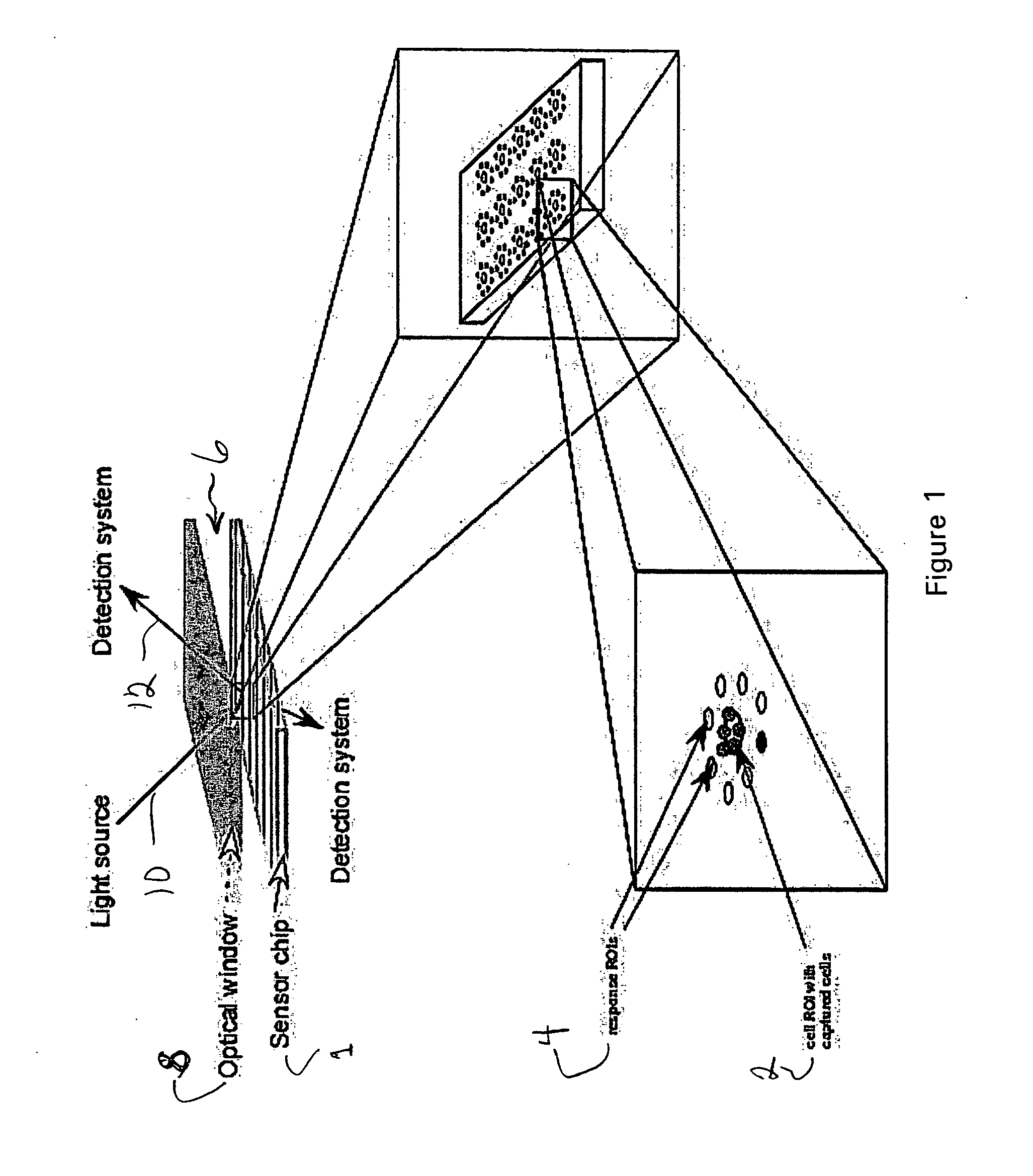
[0024]FIG. 1 illustrates an apparatus for measuring cell phenotype and cellular responses including a biosensor chip 1 onto which the cell ROIs 2 and the Response ROIs 4 are deposited in predetermined spatial patterns. A flow cell 6 that contains the biosensor chip 1, brings a sample into contact with the biosensor surface, provides a chamber for incubating cells during the course of an experiment, and provides a window 8 for optical interrogation. An optical detection system provides an illumination beam 10 and detects the reflected light 12 from the chip to measure the binding of cells and bioproducts to their cognate ROIs. One method of optical interrogation of analyte (cell or bioproduct) binding to the chip is based on the phenomenon of surface plasmon resonance (SPR). An SPR chip typically includes a reflectio...


PUM


Abstract

An assay technique for label-free, highly parallel, qualitative and quantitative detection of specific cell populations in a sample and for assessing cell functional status, cell-cell interactions and cellular responses to drugs, environmental toxins, bacteria, viruses and other factors that may affect cell function. The technique includes a) creating a first array of binding regions in a predetermined spatial pattern on a sensor surface capable of specifically binding the cells to be assayed; b) creating a second set of binding regions in specific spatial patterns relative to the first set designed to efficiently capture potential secreted or released products from cells captured on the first set of binding regions; c) contacting the sensor surface with the sample, and d) simultaneously monitoring the optical properties of all the binding regions of the sensor surface to determine the presence and concentration of specific cell populations in the sample and their functional status by detecting released or secreted bioproducts.

Description

[0001] This application claims the benefit of U.S. Provisional Application No. 60 / 691,951, filed Jun. 17, 2005.FIELD OF THE INVENTION [0002] The disclosed embodiments relate to an assay technique for the determination of phenotype and function of biological cells in a sample using an optical biosensor. BACKGROUND OF THE INVENTION [0003] Optical techniques that measure cellular phenotype and function most often employ labeled antibodies that specifically label proteins of interest. For example, immunohistochemistry employs samples that have been affixed to a slide and labeled with fluorescently or enzymatically labeled antibodies. Immunohistochemistry has been used in many contexts, including the upregulation of proteins and the characterization of cellular phenotypes. Immunofluorescence microscopy measures antigenic structure with fluorescently labeled antibodies. Uses of this technique include studies of surface expression of proteins in normal and leukemic lymphocytes, and surface...

Claims


Application Information

Patent Timeline
IPC IPC(8): C12Q1/00G01N33/567
CPCG01N33/5091Y10T436/105831Y10T436/24Y10T436/101666
Inventor LYNES, MICHAEL A.FERNANDEZ, SALVADOR M.
Owner CIENCIA
Why Eureka
Try Eureka