
Electron beam directed energy device and methods of using same

a technology of energy devices and energy devices, applied in the field of energy devices directed by electron beams, can solve problems such as unsolvable problems, mechanical steering is not fast enough, and the practical implementation is challenged, and achieves the effect of less energy to detect and less distan

Inactive Publication Date: 2007-02-08
RETSKY MICHAEL W
View PDF6 Cites 3 Cited by
  • Summary
  • Abstract
  • Description
  • Claims
  • Application Information

AI Technical Summary

Benefits of technology

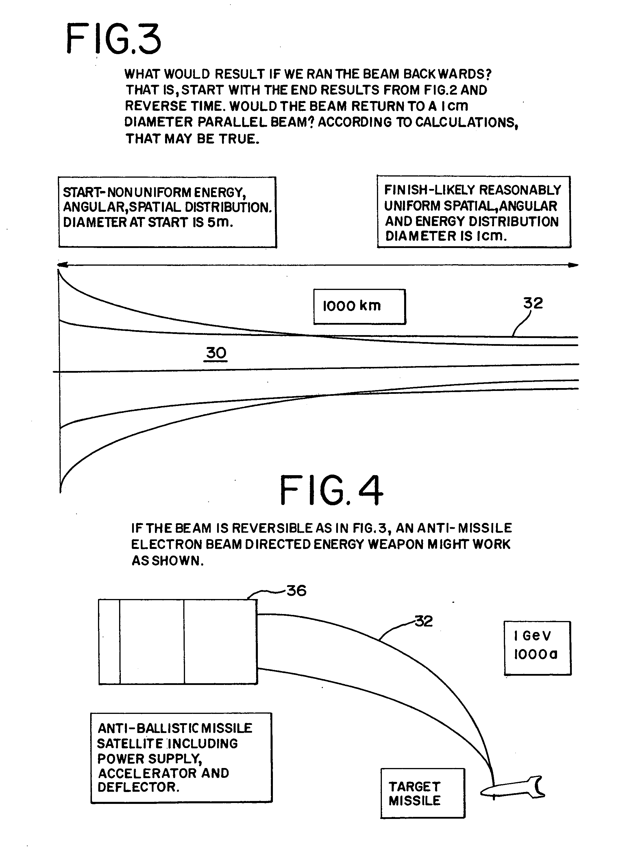
[0021] By overcoming Coulomb repulsion of electrons traveling in a beam at substantial distances, a directed energy device can be employed to impact, disable and even destroy missiles and rockets traveling both within and outside the earth's atmosphere. The same techniques for directing an electron beam can also be used at lesser distances and with less energy to detect and even destroy landmines located at or beneath the earth's surface. Both of these applications are intended to protect earth's inhabitants from the harmful and often fatal effects of devastating weapons such as missiles and landmines.

Problems solved by technology

In the above article, the authors presented many small but practical problems of particle-beam weapons such as how to generate sufficient power in space, how to deal with countermeasures, and how to find targets among decoys.
That is, the smaller problems may be considered very difficult scientific and engineering problems that may challenge practical implementation.
However, even if all those could be dealt with, two significant problems remained that were unsolvable due to fundamental physical limitations that no amount of Herculean engineering could resolve.
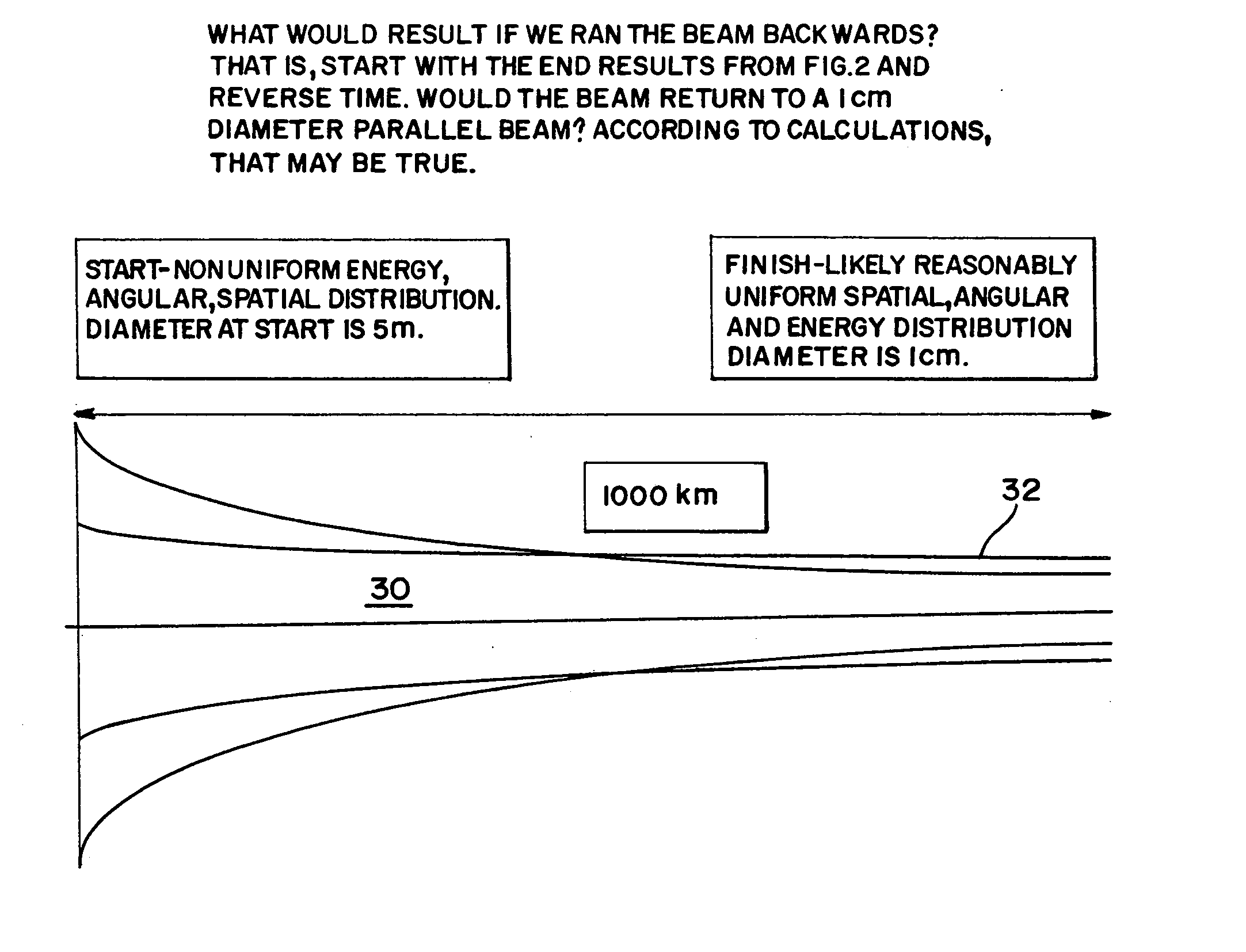
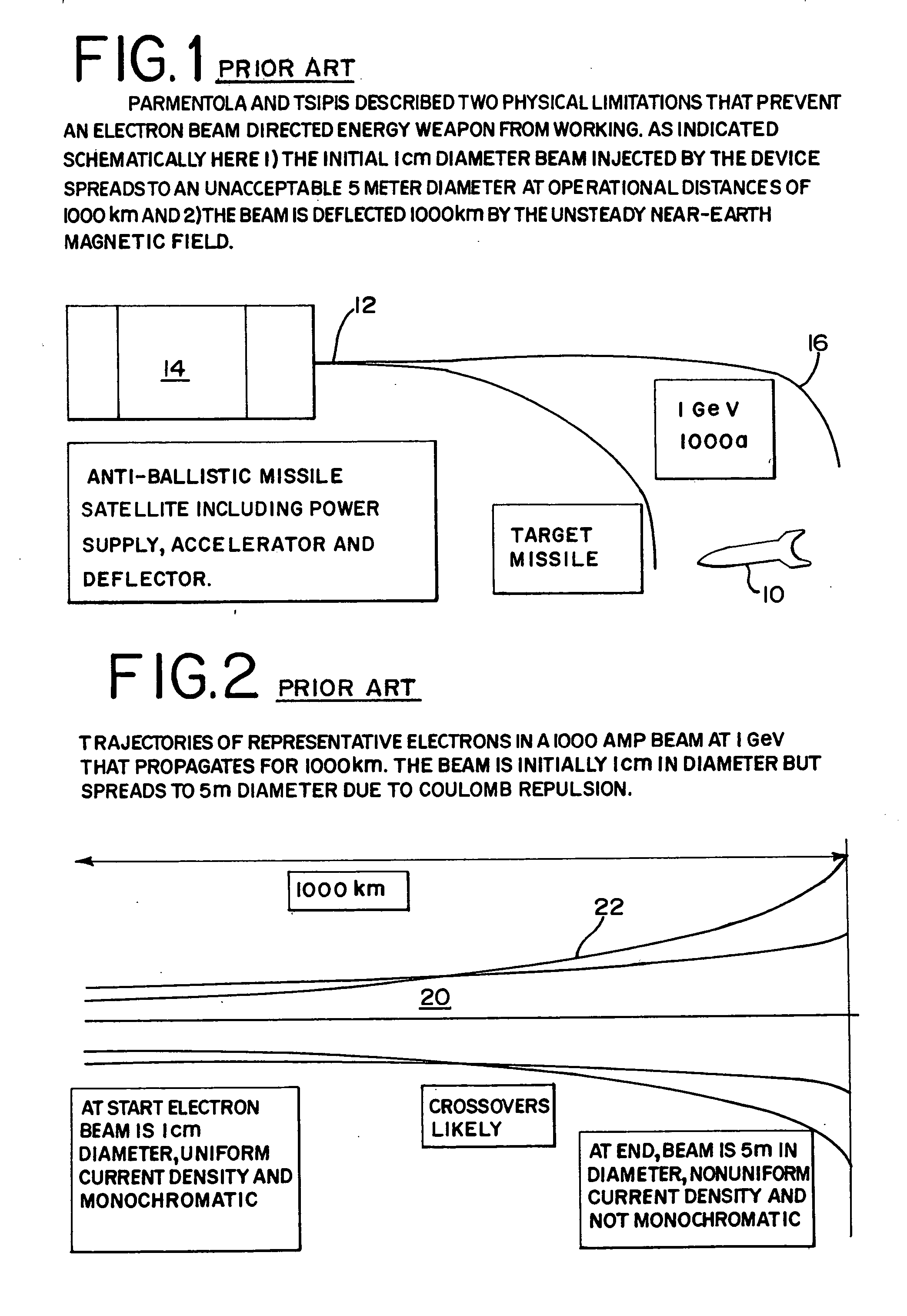
These fundamental problems are (1) that Coulomb repulsion of a particle beam spreads the energy over a large area at reasonable distances to targets, and (2) that the near-earth magnetic field deflects the beam and is somewhat variable.
Mechanical steering would not be fast enough.)
It is well known that the earth's magnetic field is also not completely steady.
Under such unstable conditions, it would be close to impossible to make a workable weapon that could reliably hit a target 1000 km away with enough energy to destroy it.
Also, there are only 400 or so seconds to distinguish between multiple targets and decoys in the initial phase of a ballistic missile's trajectory and then destroy the targets.
It is complex, but the near-earth magnetic field has both a significant predictable varying component and also a significant non-predictable varying component.
The prior art lacks a workable concept of how to use an electron beam directed energy device that can overcome Coulomb repulsion and the earth's varying magnetic field and steer the beam such that it can impact and destroy objects approximately 1000 km distant, such as missiles in outer space.
Another major unsolved problem is the detection and / or the destruction of landmines.
With landmines, an enemy is denied safe access to specific areas.
They can impede supply lines and demoralize a foe.
This will disrupt commerce, instill fear among non-combatants, and act as a psychological weapon to undermine confidence in governments.
These latter are particularly injurious to civilians including farmers and young persons playing in fields.
It is a worldwide-recognized hazard.
However, all would agree that leftover landmines are a major health and societal problem in many areas of the world.
From a technical viewpoint, finding buried landmines and concealed explosives is difficult since there is usually only access to one side of the object.
This is far less efficient than detection in a direct transmission or shadow image mode in which case there are many more measurable events per incident photon.
If there were only access to one side of a human subject, x-radiation would be practically worthless in finding occult cancer.
The prior art lacks a method using an electron beam device to produce a sub-earth surface source of x-radiation.
The prior art also lacks an electron beam device to locate or destroy buried objects including explosives.

Method used


Image

  • Electron beam directed energy device and methods of using same
  • Electron beam directed energy device and methods of using same
  • Electron beam directed energy device and methods of using same

Examples


first embodiment

[0048] Taking into account the 10 km uncertainty in beam trajectory at 1000 km due to the unpredictable component of the near-earth magnetic ambient field, there are several alternative embodiments contemplated in order to hit a 1 meter target. In a first embodiment, a line shaped beam is created and swept in a raster fashion like a broom over a 10 km by 10 km field horizontally and then vertically. While doing this, infrared telescopes (not shown) in orbit and / or earth-based are used to look for sudden heating of the target, or x-ray sensors are used to look for sudden x-ray flashes—in real time since the beam is travelling essentially at the speed of light. When a heat surge or x-ray, or any other emission from that target is detected, it can be correlated to the beam position so that the target can be located and / or destroyed in short time.

second embodiment

[0049] There are other ways to solve this location problem. In a second embodiment, knowing the magnetic field to 1 part in 107 between the gun and target (mostly near the gun), or alternatively using an array of distant test targets that can be used for trajectory calibration, can be used to aim or locate the beam. This is analogous to a target-shooter who can either know the wind at all points between him and the target or take a few test shots for calibration. The first may be impractical, but the second is not. The electron gun preferably sends lower energy bursts at full beam voltage to test targets strategically placed to obtain feedback on magnetic deflection.

[0050] The preferred device would not operate well in a vacuum worse than 10−6 torr due to unacceptable corona effects. If the orbital environment is not that good (lower than 500-600 km orbit), the entire gun can be contained within a sealed enclosure and exhausted down to required vacuum levels. A thin conductive membr...


PUM


Abstract

A method and apparatus is disclosed for an electron beam directed energy device. The device consists of an electron gun with one or more electron beams. The device includes one or more accelerating plates with holes aligned for beam passage. The plates may be flat or preferably shaped to direct each electron beam to exit the electron gun at a predetermined orientation. In one preferred application, the device is located in outer space with individual beams that are directed to focus at a distant target to be used to impact and destroy missiles. The aimings of the separate beams are designed to overcome Coulomb repulsion. A method is also presented for directing the beams to a target considering the variable terrestrial magnetic field. In another preferred application, the electron beam is directed into the ground to produce a subsurface x-ray source to locate and / or destroy buried or otherwise hidden objects including explosive devices.

Description

RELATED APPLICATIONS [0001] The present patent document claims the benefit of the filing date under 35 U.S.C. §119(e) of Provisional U.S. Patent Application Ser. No. 60 / 591,219 filed Jul. 26, 2004, the contents of which are incorporated herein by reference.FEDERALLY SPONSORED RESEARCH OR DEVELOPMENT [0002] This invention was made in part while under contract DE-FG36-01GO11021 with the Department of Energy.BACKGROUND OF THE INVENTION [0003] This invention relates to electron beam directed energy devices. In particular, this invention is directed to an electron beam device that can be used as a directed energy weapon and with modifications as a landmine detection device. [0004] Peaking a few decades ago, there has been ongoing interest in the concept of using particle accelerators in space as weapons to destroy ballistic missile targets above the atmosphere. While much of this has been kept confidential for national security reasons, Parmentola and Tsipis presented a landmark paper on...

Claims


Application Information

Patent Timeline
Patent Type & Authority Applications(United States)
IPC IPC(8): H01J3/14
CPCF41H11/02F41H11/12F41H13/00F41H11/136H01J3/02H01J3/026H01J3/14F42B33/065F41H13/0043
Inventor RETSKY, MICHAEL W.
Owner RETSKY MICHAEL W
Learn More