Electrostatic ultrasonic transducer, ultrasonic speaker, audio signal reproduction method, electrode manufacturing method for use in ultrasonic transducer, ultrasonic transducer manufacturing method, superdirective acoustic system, and display device

a technology of electrostatic ultrasonic transducers and manufacturing methods, applied in the direction of transducers, generators/motors, mechanical vibration separation, etc., can solve the problems of modulation wave itself suffering from distortion, sound pressure is thus somewhat insufficient for use as an ultrasonic speaker, and achieve the effect of exercising control over the reproduction range of acoustic signals

Inactive Publication Date: 2007-02-08
SEIKO EPSON CORP
View PDF9 Cites 34 Cited by
  • Summary
  • Abstract
  • Description
  • Claims
  • Application Information

AI Technical Summary

Benefits of technology

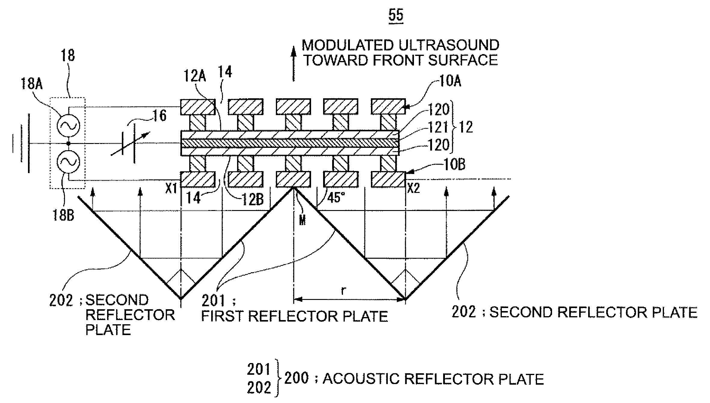
[0107] As such, the acoustic signal can be reproduced with a sufficient level of sound pressure in a wide range of frequency from a virtual sound source, which is formed in the vicinity of an acoustic wave reflector plate exemplified by a screen. This accordingly enables to exercise control with ease over the reproduction range of the acoustic signal.

Problems solved by technology

The problem with such an electrostatic ultrasonic transducer is that, as shown in FIG. 18, the maximum sound pressure is low as 120 dB or lower compared with the sound pressure of 130 dB or higher for the ultrasonic transducer of resonance type.
The sound pressure is thus somewhat not enough for use as an ultrasonic speaker.
As a result, the modulation wave itself suffers from distortion, and is subjected to curve fitting to derive a carrier wave (ultrasound) and an audible wave (original audio signal).
The electrostatic ultrasonic transducer, however, has a difficulty in achieving this value, and thus a ceramic piezoelectric device made of PZT (lead zirconate titanate) or a polymer piezoelectric device made of PVDF (polyvinylidene fluoride) has been used as an ultrasound transmitter.
The issue here is that a resonance point of the piezoelectric device forms a sharp angle irrespective of the material, and the resonance frequency is used for driving so that the ultrasonic speaker is put in practical use.
Actually, there have been problems with an ultrasonic speaker using the previous ultrasonic speaker of resonance type, e.g., narrow bandwidth with bad audio reproduction quality, the maximum degree of modulation is of about 0.5 because if the degree of AM modulation is increased too much, the demodulated audio will sound distorted, increasing an input voltage (increasing volume) causes unstable oscillation of a piezoelectric device and the audio thus sounds raspy, and a higher voltage easily damages the piezoelectric device, and difficulties in array configuration, size increase, and size reduction, thereby resulting in cost increase.
Although the ultrasonic speaker can cover a wide range of bandwidth, there is still a problem of the shortage of absolute sound pressure to derive sufficient volume for the demodulated audio.
The electrostatic ultrasonic transducer of Pull type has also a problem if it is used for an ultrasonic speaker.
Even with such an electrostatic ultrasonic transducer of Push-Pull type, however, if no change is made thereto, there is still a difficulty in generating the sufficient level of sound pressure in the air.
As such, even the electrostatic ultrasonic transducer of such Push-Pull type is not yet enough to generate the sufficient level of sound pressure.
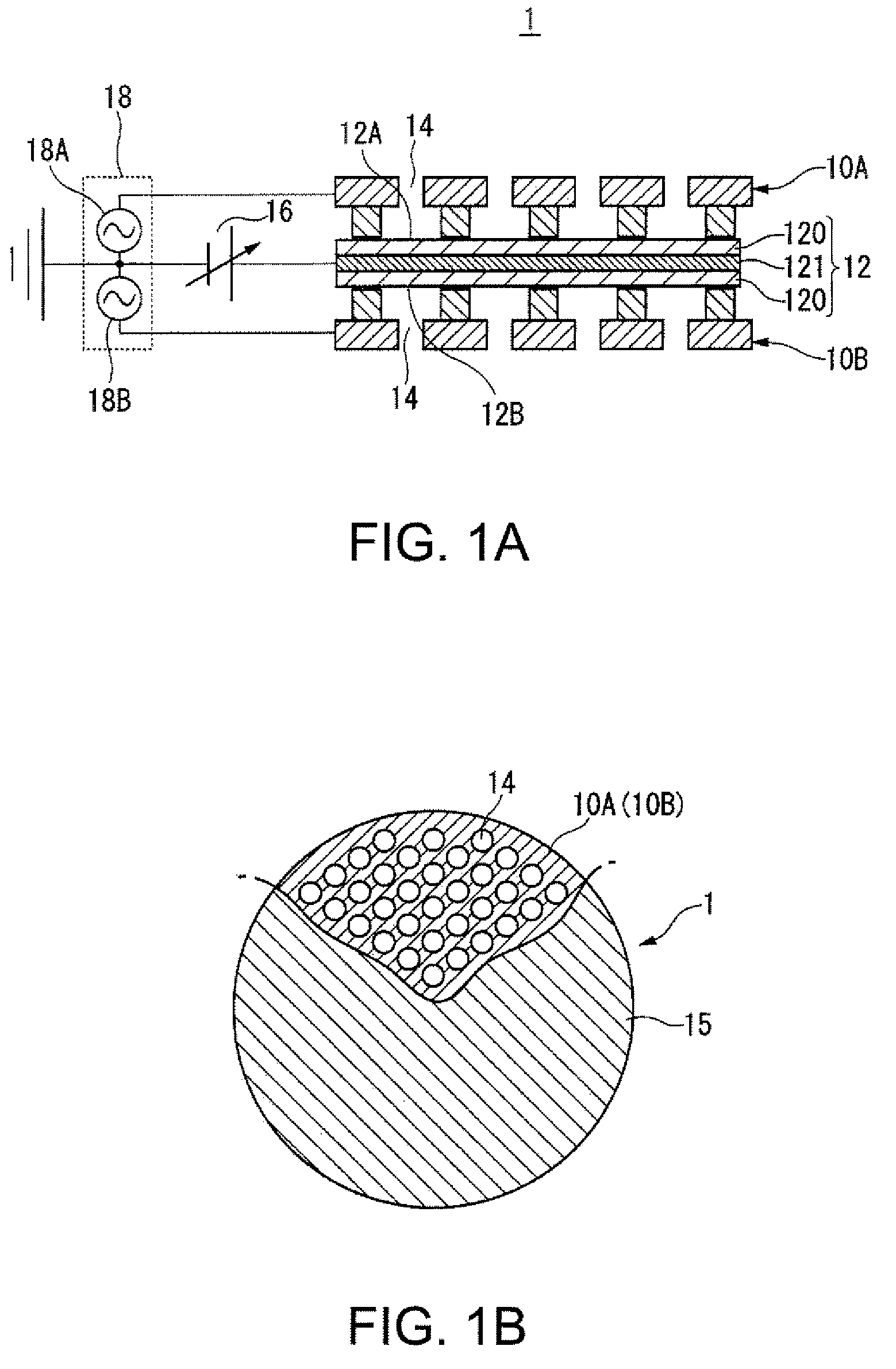
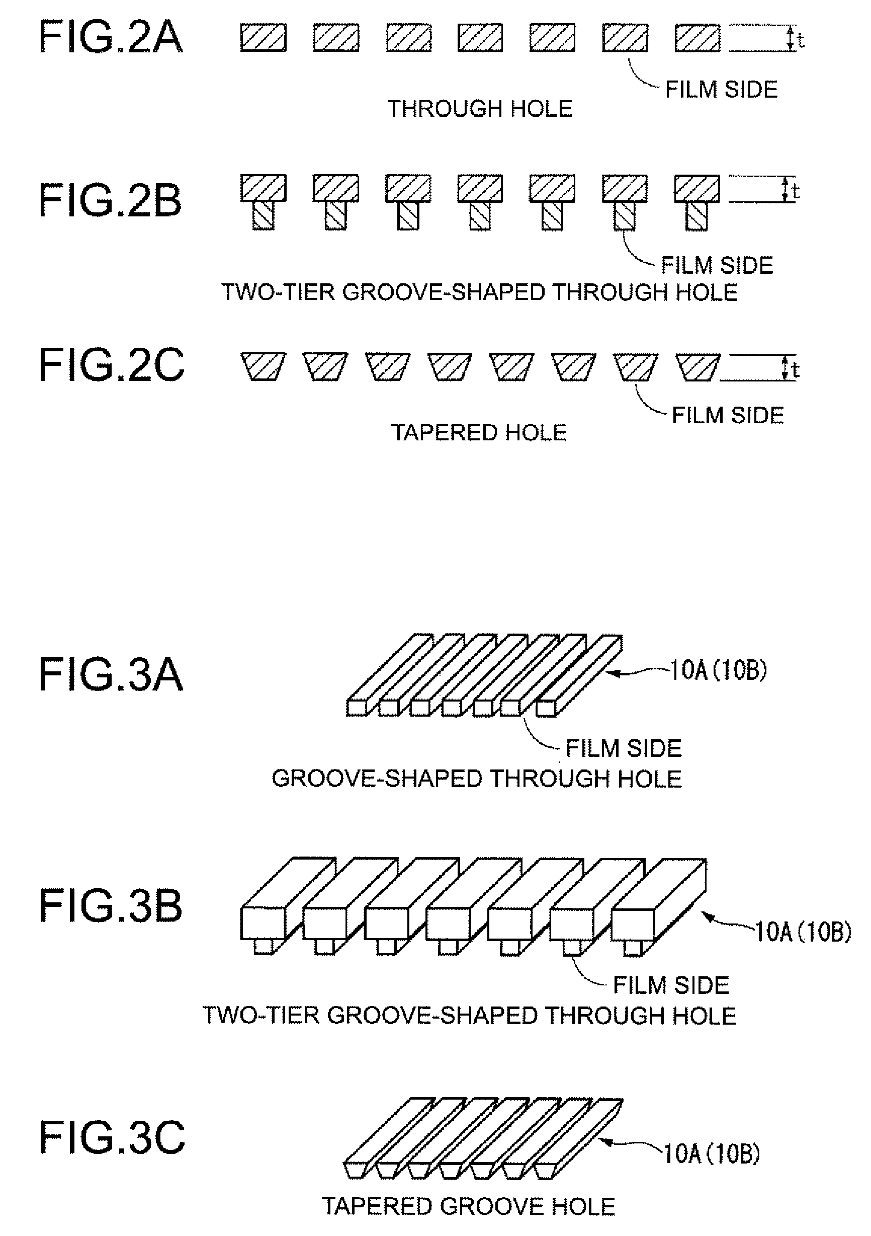
The advantage of the cylindrical through holes is that they can be manufactured in the easiest manner, and the drawback thereof is that the electrostatic force acting between the conductor layer of the oscillation film is weak because the side of the electrode has no electrode portion facing the oscillation film.
The advantage of the through holes each configured to have a rectangular plane surface as such is that they can be manufactured in the easiest manner, and the drawback thereof is that the electrostatic force acting between the conductor layer of the oscillation film is weak because the side of the electrode has no electrode portion facing the oscillation film.

Method used


Image

  • Electrostatic ultrasonic transducer, ultrasonic speaker, audio signal reproduction method, electrode manufacturing method for use in ultrasonic transducer, ultrasonic transducer manufacturing method, superdirective acoustic system, and display device
  • Electrostatic ultrasonic transducer, ultrasonic speaker, audio signal reproduction method, electrode manufacturing method for use in ultrasonic transducer, ultrasonic transducer manufacturing method, superdirective acoustic system, and display device
  • Electrostatic ultrasonic transducer, ultrasonic speaker, audio signal reproduction method, electrode manufacturing method for use in ultrasonic transducer, ultrasonic transducer manufacturing method, superdirective acoustic system, and display device

Examples


first embodiment

Manufacturing Method for use in Electrostatic Ultrasonic Transducer of Invention

[0233]FIGS. 9A to 9E show a first embodiment of a fixed electrode manufacturing method for use in the electrostatic ultrasonic transducer of the invention.

[0234] In FIGS. 9A to 9E, first of all, the conductor plate 10C is covered by the mask member 11 formed with a pattern of a plurality of through holes, and the conductor plate 10C is formed with the through holes 14 by etching (FIGS. 9A and 9B). Herein, the conductor plate 10C is often made of copper or stainless, and if for nickel electroforming, the plate is suitably made of copper.

[0235] After the conductor plate 10C is formed with the through holes 14, the mask member 11 is peeled off so that the resulting conductor plate 10C is punched with the through holes 14 (FIG. 90C). The resulting conductor plate 10C is then stacked with others to have the thickness t of about (λ / 4)·n (where λ denotes a wavelength of ultrasound, and n denotes a positive od...

second embodiment

anufacturing Method for use in Electrostatic Ultrasonic Transducer of Invention (Screen Printing)

[0240]FIGS. 10A to 10E show a second embodiment of the fixed electrode manufacturing method (manufacturing process) for use in the electrostatic ultrasonic transducer of the invention.

[0241] In FIGS. 10A to 10E, first of all, the conductor plate 10C is covered by the mask member 11 formed with a pattern of a plurality of through holes, and the conductor plate 10C is formed with the through holes 14 by etching (FIGS. 10A and 10B). Herein, the conductor plate 10C is often made of copper or stainless, and if for nickel electroforming, the plate is suitably made of copper.

[0242] After the conductor plate 10C is formed with the through holes 14, the mask member 11 is peeled off so that the resulting conductor plate 10C is punched with the through holes 14 (FIG. 10C). The resulting conductor plate 10C is stacked with others to have the thickness t of about (λ / 4)·n (where λ denotes a waveleng...


PUM


Abstract

An electrostatic ultrasonic transducer that includes: a first electrode that is formed with a plurality of holes; a second electrode that is formed with a plurality of holes, and is used in pair with the first electrode; an oscillation film formed with a conductor layer that is sandwiched between the pair of electrodes, and the conductor layer is applied with a direct-current (DC) bias voltage; and a retention member that keeps hold of the pair of electrodes and the oscillation film. In the transducer, an alternating signal is applied between the pair of electrodes, and the pair of electrodes each have a thickness t of about (λ/4)·n (where k denotes a wavelength of ultrasound, and n denotes a positive odd number).

Description

BACKGROUND [0001] 1. Technical Field [0002] The present invention relates to an electrostatic ultrasonic transducer that generates a high sound pressure of a fixed level over a wide range of frequency, an ultrasonic speaker using the same and an audio signal reproduction method using the electrostatic ultrasonic transducer, an electrode manufacturing method for use in an ultrasonic transducer, an ultrasonic transducer manufacturing method, a superdirective acoustic system, and a display device. [0003] 2. Related Art [0004] Most of the previous ultrasonic transducers are of resonance type using a piezoelectric ceramic material. [0005]FIG. 16 shows the configuration of the previous ultrasonic transducer. Most of the previous ultrasonic transducers are of resonance type using a piezoelectric ceramic material for an oscillator. Using the piezoelectric ceramic material for an oscillator, the ultrasonic transducer of FIG. 16 performs conversion from an electric signal to ultrasound and fr...

Claims


Application Information

Patent Timeline
Patent Type & Authority Applications(United States)
IPC IPC(8): H04R19/00H01L41/00H04R1/40H04R3/00H04R19/02
CPCH04R19/013B06B1/0292
Inventor MATSUZAWA, KINYA
Owner SEIKO EPSON CORP
Why Eureka
Try Eureka