Littrow spectrometer and a spectral domain optical coherence tomography system with a littrow spectrometer

a technology of optical coherence tomography and littrow spectrometer, which is applied in the field of optical spectrometers, can solve the problems of large spectrometer size, large incident beam distortion, and spectrometer output being very sensitive to the tip movement of the focused spectral line with respect to the linear array pixels, so as to reduce non-linearities

Active Publication Date: 2007-02-08
CARL ZEISS MEDITEC INC
View PDF25 Cites 65 Cited by
  • Summary
  • Abstract
  • Description
  • Claims
  • Application Information

AI Technical Summary

Benefits of technology

[0013] The orientation of the grating is tilted or tipped to induce conical diffraction in order to spatially separate the incoming beam from the diffracted beams to be measured. The conical diffraction

Problems solved by technology

However, due to the large extent of the dispersed spectrum in the plane of the incident and dispersed beams, the incident and diffracted beams generally do not share a common lens, as doing so would put the incident beam at a large off-axis angle, which tends to cause distortion in the incident beam and this distortion carries through to the diffracted beams.
A problem associated with such a design is that the size of the spectrometer will be large and in addition, when a standard high speed (>1000 lines/sec) line scan camera is used as the detector array, owing to the small height of the linear arr

Method used


Image

  • Littrow spectrometer and a spectral domain optical coherence tomography system with a littrow spectrometer
  • Littrow spectrometer and a spectral domain optical coherence tomography system with a littrow spectrometer
  • Littrow spectrometer and a spectral domain optical coherence tomography system with a littrow spectrometer

Examples


Embodiment Construction

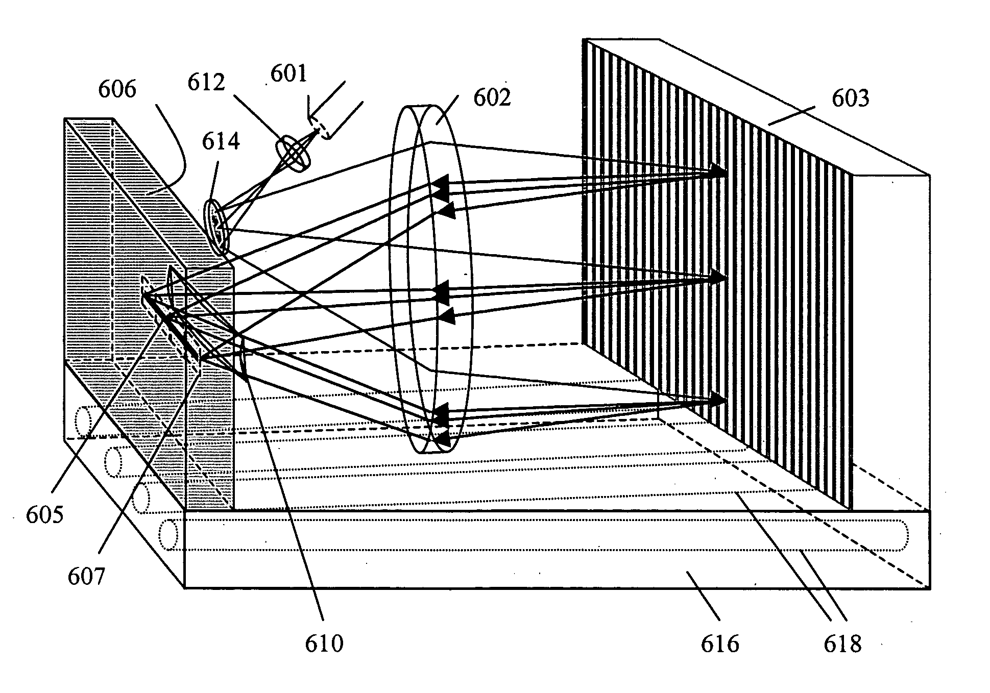
[0036] As is well known to those skilled in the art, a broad band light beam can be dispersed into its spectral components in a number of ways, including the use of a prism, a grating, an arrayed waveguide grating or a combination of optical filters. A grating is generally used in most spectrometers because of its high resolving power and hence high spectral resolution within a limited space. In many applications, a plane grating is preferred because of its low cost as compared to other more complex gratings such as a curved grating, a volume holographic grating, or a photonic crystal grating.

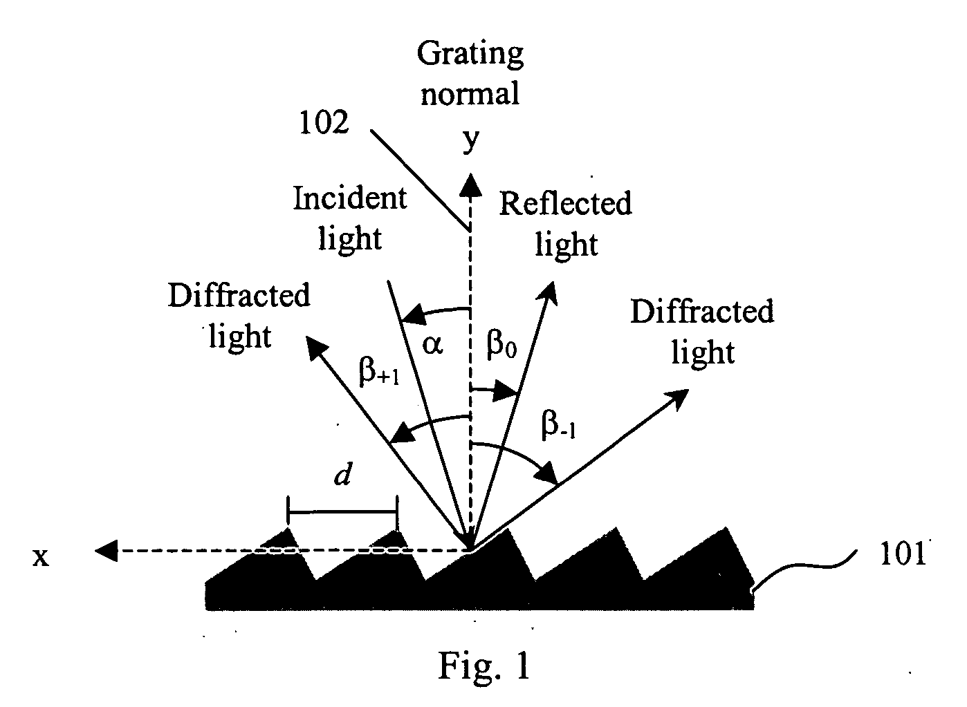
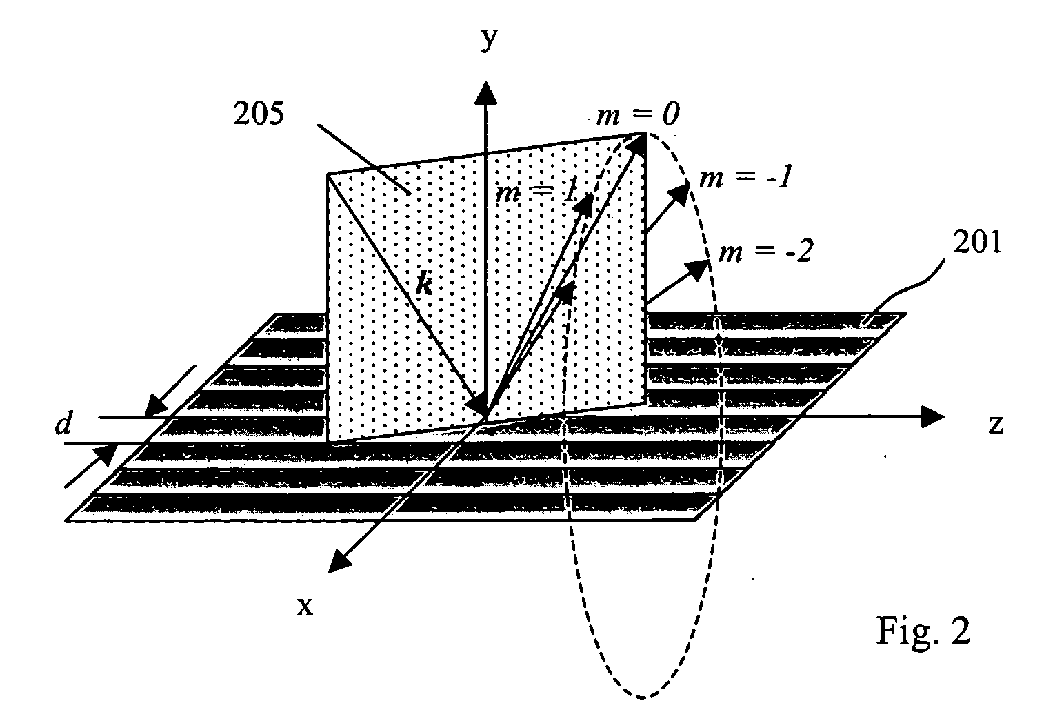
[0037]FIG. 1 shows the case of a plane reflection grating 101, the grating equation is given by

mλ=d(sin α+sin βm)  (1)

where m is the diffraction order which is an integer, λ is the wavelength of light, d is the grating period, α is the angle of incidence, and βm is the angle of diffraction. The angle of incidence and angle of diffraction are measured from the grating normal 102, i.e. the da...


PUM


Abstract

A compact conical diffraction Littrow spectrometer is disclosed. The distortion of the conically diffracted spectral component beams is compensated and as a result, the diffracted spectral beams can still be focused into a substantially straight line to shine onto a detector array. A spectral domain optical coherence tomography (SD-OCT) system incorporating a Littrow spectrometer or a spectrometer having one or more shared focusing element(s) and an SD-OCT system incorporating a spectrometer that is substantially polarization independent are also disclosed.

Description

BACKGROUND OF THE INVENTION [0001] 1. Field of the Invention [0002] The invention relates generally to optical spectrometers and to the use of a Littrow configuration spectrometer in a spectral domain optical coherence tomography system. [0003] 2. Description of Related Art [0004] Optical Coherence Tomography (OCT) is a technology for performing high-resolution cross sectional imaging that can provide images of tissue structure on the micron scale in situ and in real time. In recent years, it has been demonstrated that spectral domain OCT has significant advantages in speed as compared to time domain OCT. In spectral domain OCT, the optical path length difference between the sample and reference arm is not mechanically scanned but rather the interferometrically combined beam is sent to a spectrometer in which different wavelength components are dispersed onto different photodetectors to form a spatially oscillating interference fringe (Smith, L. M. and C. C. Dobson (1989). “Absolute...

Claims


Application Information

Patent Timeline
IPC IPC(8): G01J3/28
CPCG01J3/02G01J3/0205G01J3/0208G01J3/0216G01J3/0224G02B27/4244G01J3/0286G01J3/18G01J3/22G01N21/4795G02B5/1814G01J3/0256A61B3/102G01B9/02044G01B9/02091
Inventor EVERETT, MATTHEWZHOU, YANHORN, JOCHENO'HARA, KEITHFOLEY, JAMES
Owner CARL ZEISS MEDITEC INC
Why Eureka
Try Eureka