High dynamic range imaging device using multiple pixel cells

a high dynamic range and imaging device technology, applied in the field of high dynamic range imaging device using multiple pixel cells, can solve the problems of limited dynamic range on the upper end, danger of overexposure, danger of underexposure, etc., and achieve low fixed pattern noise, high sensitivity to light, and high dynamic range

Active Publication Date: 2007-02-15
APTINA IMAGING CORP
View PDF11 Cites 75 Cited by
  • Summary
  • Abstract
  • Description
  • Claims
  • Application Information

AI Technical Summary

Benefits of technology

[0013] Exemplary embodiments of the invention provide a set of spatially distributed pixel cells having different light response sensitivities to provide a high dynamic range with low fixed pattern noise. At least one pixel cell of the spatially distributed set of pixel cells has high sensitivity to light so that it becomes easily saturated and yields good resolution for dark signals. At least one other pixel cell of the set has a lower sensitivity to light such that it is slowly saturated with a bright signal. The sensitivity of the at least two pixel cells of the set is controlled by the sizes of apertures in a light-blocking layer, and a light transparent neutral density filter layer to control the light sensitivity of the at least two pixel cells of the set. Each of the apertures have different individual neutral density filter layers providing different light sensitivities to each respective pixel cell of the set. A method of forming a pixel array containing the light blocking layer and neutral density filter layer is also provided.

Problems solved by technology

One common problem associated with solid-state imaging devices, including CCD and CMOS imaging devices, is consistency in a pixel cell's responsivity to light incident on the light sensing element across an array of pixel cells.
Dynamic range is limited on an upper end by the charge saturation level of the image sensor, and on a lower end, by noise imposed limitations and / or quantization limits of the analog to digital converter used to produce the digital image.
However, for any given integration period, in the presence of incident light having a high level of brightness, there is a danger of overexposure due to the photosensor 12 producing too many photo-generated charges.
Conversely, in the presence of incident light having a low level of brightness, there is a danger of underexposure due to the photosensor 12 producing too few photo-generated charges.
As mentioned above, blooming or saturation is a problem that occurs when too many photons strike a particular pixel cell and overflow into adjacent pixel cells, which causes the adjacent pixel cells to incorrectly sense the image.

Method used


Image

  • High dynamic range imaging device using multiple pixel cells
  • High dynamic range imaging device using multiple pixel cells
  • High dynamic range imaging device using multiple pixel cells

Examples


Embodiment Construction

[0029] In the following detailed description, reference is made to the accompanying drawings which form a part hereof, and in which is shown by way of illustration specific embodiments in which the invention may be practiced. These embodiments are described in sufficient detail to enable those skilled in the art to practice the invention, and it is to be understood that other embodiments may be utilized, and that structural, logical and electrical changes may be made without departing from the spirit and scope of the present invention.

[0030] Additionally, processing steps described and their progression are exemplary of preferred embodiments of the invention; however, the sequence of steps is not limited to that set forth herein and may be changed as is known in the art, with the exception of steps necessarily occurring in a certain order.

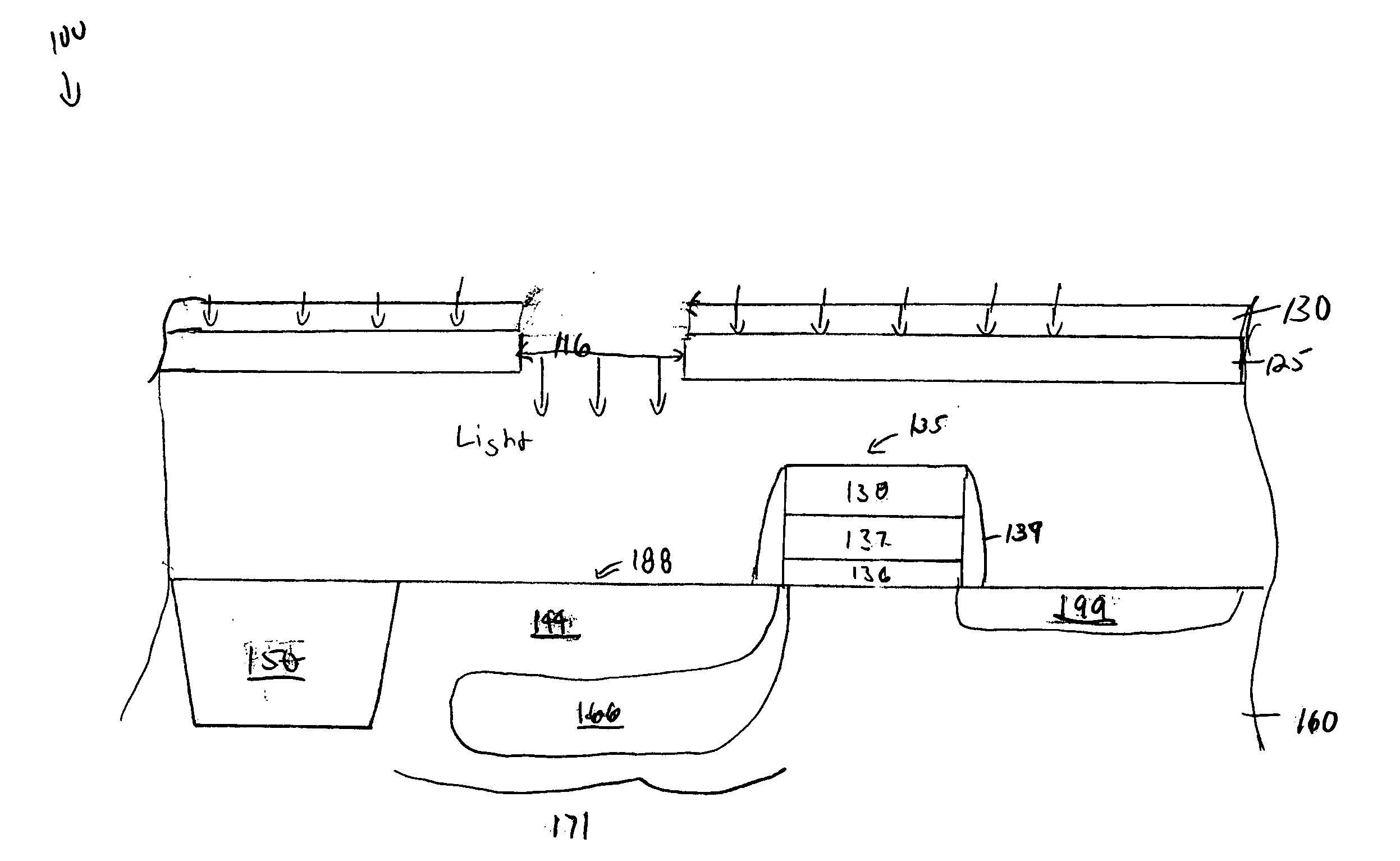
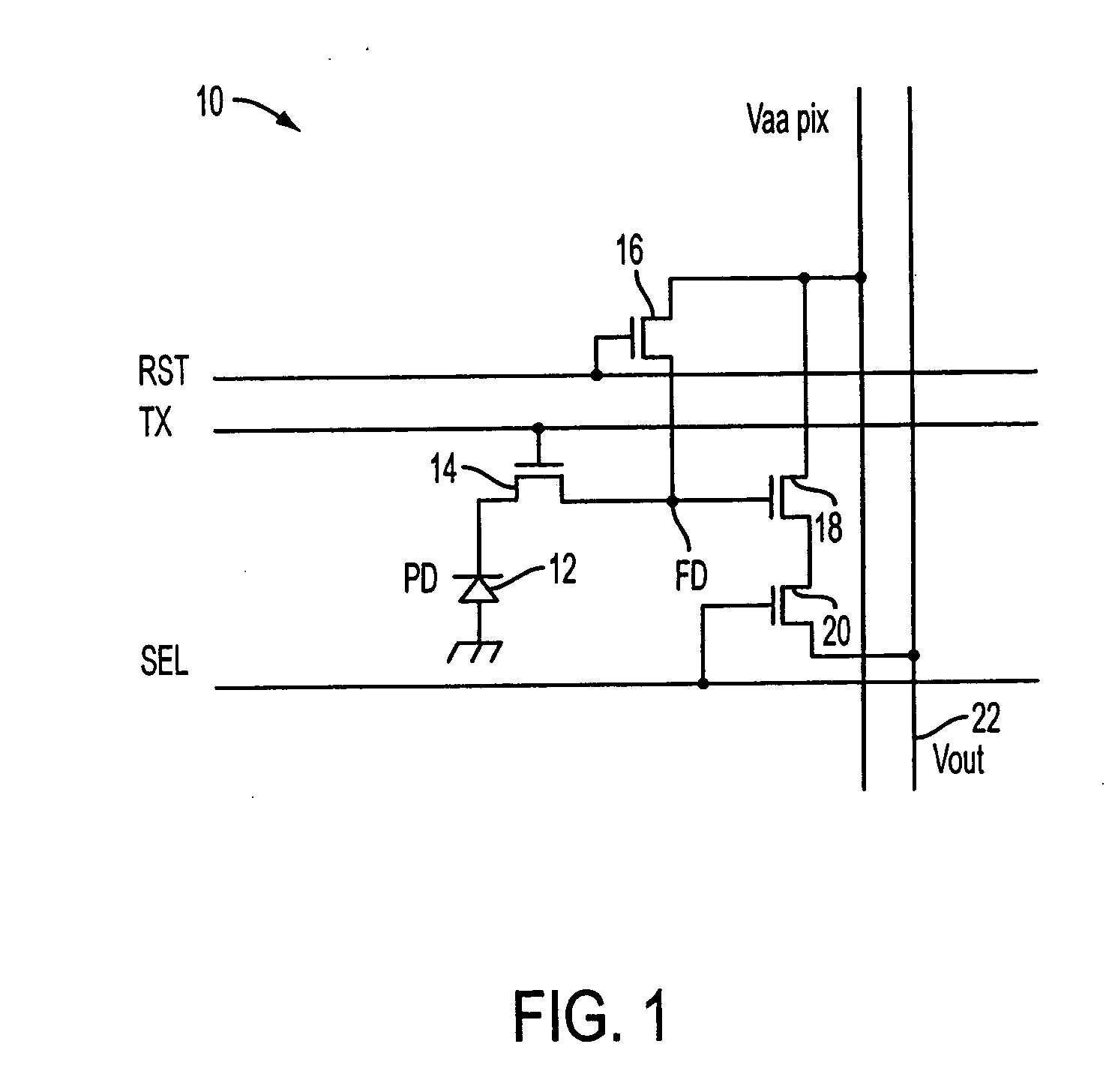
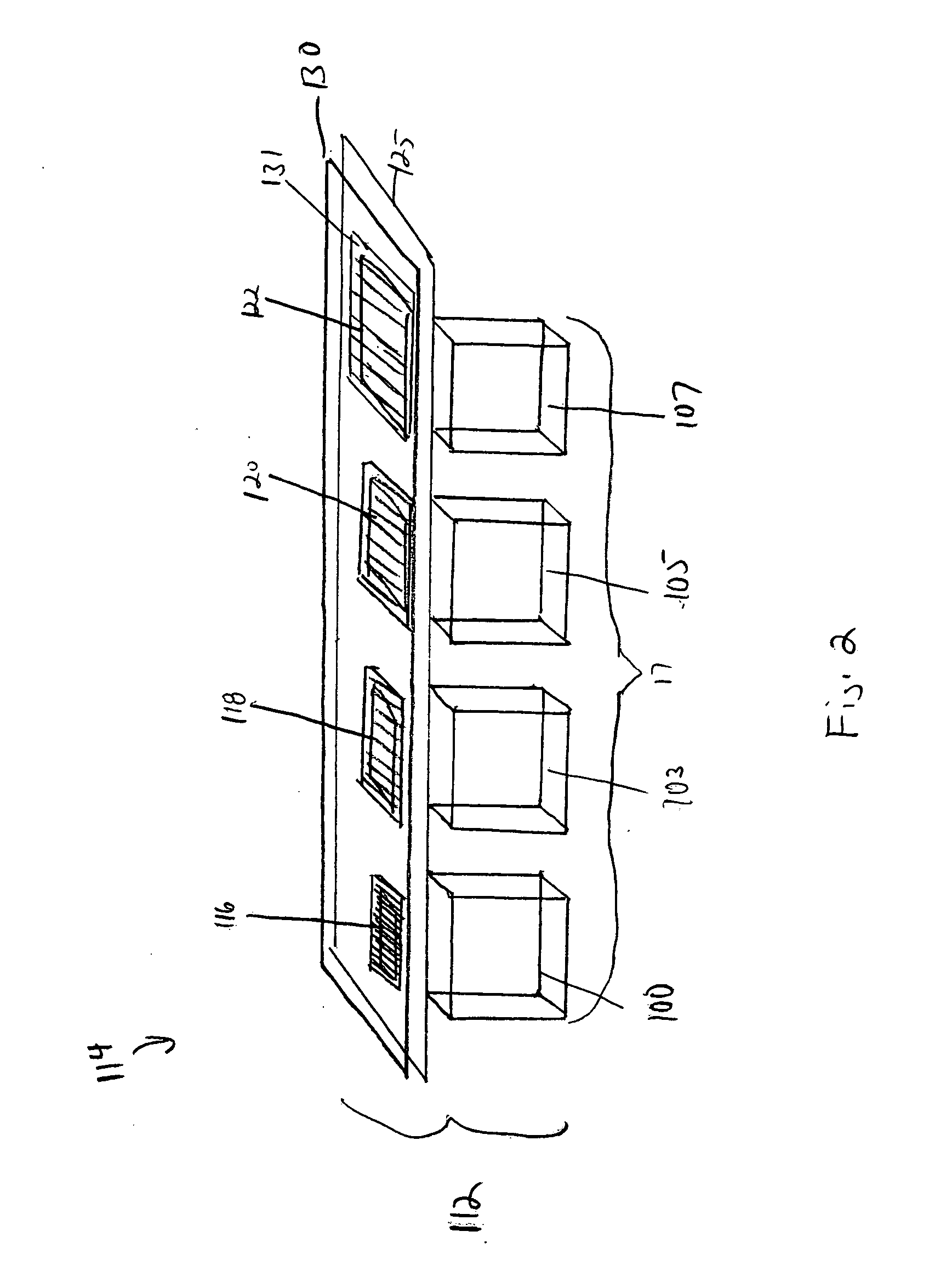
[0031] The term “substrate” is to be understood as including silicon, silicon-on-insulator (SOI) or silicon-on-sapphire (SOS) technology, doped ...


PUM


Abstract

A method and apparatus for achieving high-dynamic range operation with a set of spatially distributed pixel cells is provided. A pixel array with a row of pixels having apertures of varying sizes in a metal mask formed thereon controls the sensitivity of each pixel cell to light. A neutral density filter having varying light transparency values is also provided over the set of pixel cells to control the sensitivity of each pixel cell to light. The pixel cells voltage outputted is combined to obtain high-dynamic range operation.

Description

FIELD OF THE INVENTION [0001] The present invention relates generally to a structure and method of obtaining a high-dynamic range image by using a set of spatially distributed pixel cells that have varying degrees of sensitivity to light incident on the individual pixel cells, and a method of making the same. BACKGROUND OF THE INVENTION [0002] Imaging devices typically employ a sensor to detect light, and in response, generate an electrical signal representative of the light incident on the sensor. The sensor typically employs a light sensing element such as a photodiode, and associated circuitry for selectively reading out the electric signal provided by the light sensing element. For example, light photons impinge upon the photodiode and are converted into electrons that constitute the electrical signal. Currently there are several known types of solid-state imaging devices. The two primary types of imaging devices are CCD (charge coupled device) devices and CMOS devices. [0003] A...

Claims


Application Information

Patent Timeline
Patent Type & Authority Applications(United States)
IPC IPC(8): H04N5/225H04N5/355H04N5/369
CPCG06T5/50H04N5/235H04N5/35563H04N5/335H04N5/2355H04N23/70H04N23/741H04N25/00H04N25/585
Inventor HONG, CHRIS SUNGKWONMCKEE, JEFFREY A.
Owner APTINA IMAGING CORP
Why Eureka
Try Eureka