
Three dimensional radiation detector

a three-dimensional radiation and detector technology, applied in the field of semiconductor radiation detectors, can solve the problems of high low production yield of such a detector, and the possibility of having defects in the crystal volume from which the detector is sliced, so as to achieve accurate reconstruction of the path of photons and high volume detection utilization of the detector assembly.

Inactive Publication Date: 2007-02-22
ORBOTECH LTD
View PDF17 Cites 16 Cited by
  • Summary
  • Abstract
  • Description
  • Claims
  • Application Information

AI Technical Summary

Benefits of technology

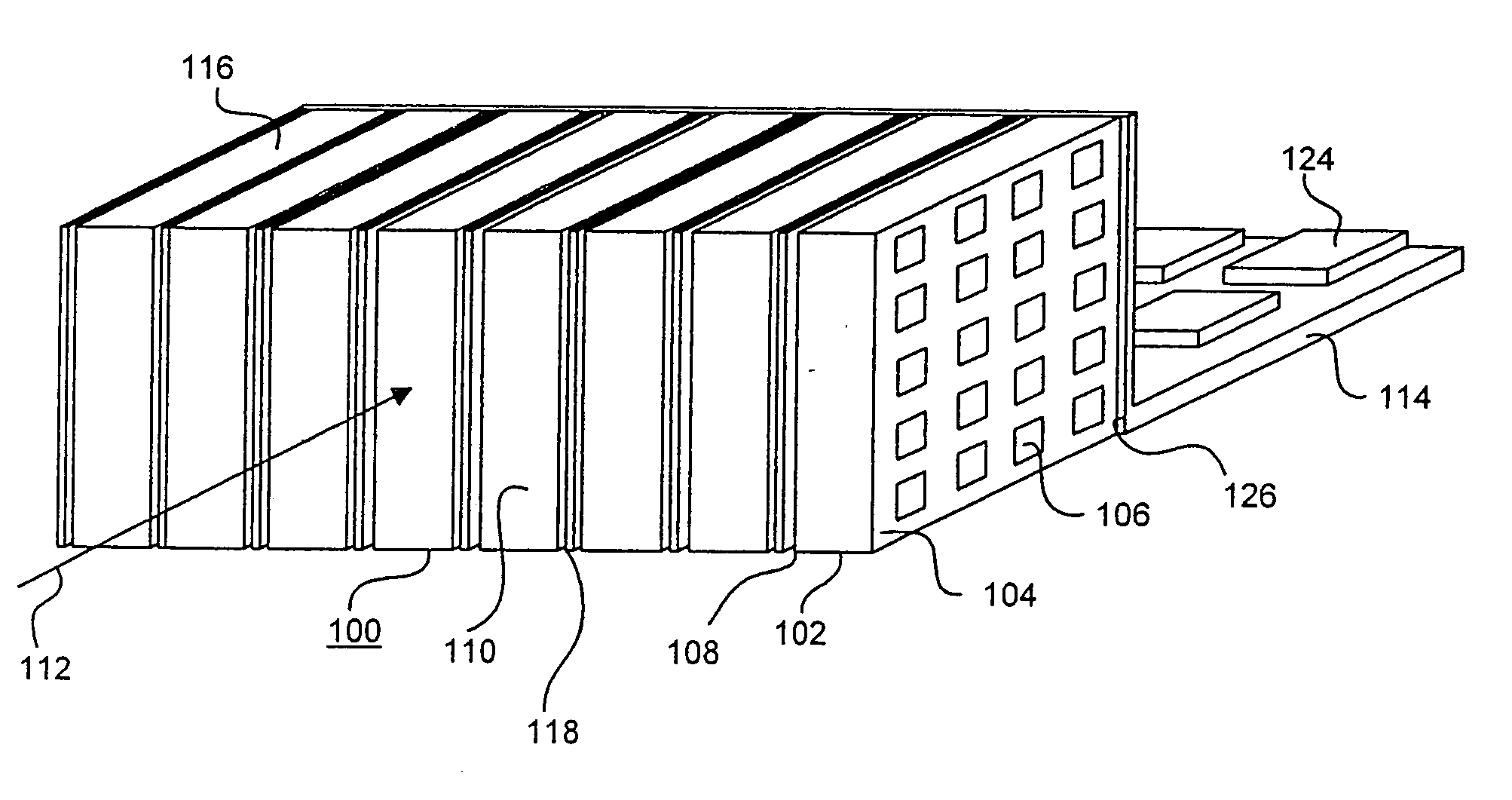
The present invention provides a new radiation detector that can absorb substantially all incident high energy photons and determine the depth of interaction of the photons in all three dimensions. This detector is advantageously thick enough to absorb all photons, but without the limitations of previous detectors such as low yield, leakage current, and difficulty in distinguishing multiple events. The detector is made up of thin detector crystals arranged in a stack, with the edges of the crystals parallel to the direction of incident radiation. Each detector crystal has a planar surface bound by edges, which are thinner than the dimensions of the crystal. The detector assembly is capable of detecting the point of interaction of a photon in the detector in all three dimensions. A connector circuit board is used to make electrical contact with the detector crystals and the circuitry is located at the back of the detector assembly to maximize detection utilization. The detector can be used in a gamma ray camera or a Compton telescope camera.

Problems solved by technology

Firstly, the probability of having defects in the crystal volume from which the detector is sliced increase dramatically with the thickness of the detector.
Consequently, the production yield of such a detector is very low.
However, because of the series current through all of the detector layers, the thickness of such a stack is limited.
The simple single slab detector described in the prior art is unable to able to determine the DOI.
Furthermore, the stacked detectors disclosed in the above-mentioned U.S. patent application Ser. No. 09 / 123,754 cannot determine the particular layer in which the absorption takes place, since equivalently located pixels of all of the layers are connected in series.
180-185, but they are complex and inaccurate, especially when used in high energy detection schemes.
The result is a very high operating voltage, which is more difficult to generate and manage, and which may present a safety hazard.
In addition, such an increase in the applied voltage causes the leakage current to increase by the same factor, and results in degradation of the detector energy resolution ability.
Fourthly, as a result of the increase in detector thickness, the transit time of the charge carriers across the detector may become longer than the time window used to identify a coincidence event between the two detectors of a PET Gamma camera.
In such a case, it may be impossible to use coincidence methods as an electronic collimator.
However the technique described in this application is not easy to implement.
Finally, when high-energy photons are detected in a thick detector, the probability of the occurrence of multiple events, by Compton scattering, may become comparatively significant, and such multiple events render it impossible to define the source location of the event producing the relevant detected photons.
However, the described detector is unable to provide any Depth of Interaction information, and thus has no three dimensional detection capabilities.
As a result, it cannot be usefully used in PET cameras, since without DOI information, parallax effects prevent the unambiguous determination of the location of the source of the emitted photons in the subject's body.

Method used


Image

  • Three dimensional radiation detector
  • Three dimensional radiation detector
  • Three dimensional radiation detector

Examples


Embodiment Construction

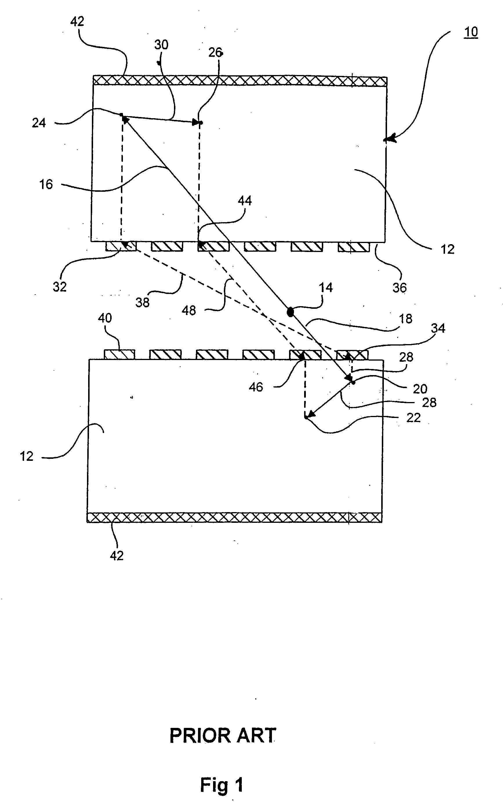
[0026] Reference is now made to FIG. 1, which illustrates schematically a two-headed Gamma ray camera 10 including two identical thick conventional prior art pixelated semiconductor detectors 12, designed to detect high-energy radiation produced by positron emission at point 14, whose location is to be imaged. From point 14 photons 16 and 18 are emitted with the same energy and along oppositely directed directions. Photon 18 might be absorbed at point 20 or alternatively might be scattered by Compton scattering as photon 28 to be absorbed at point 22. Similarly, photon 16 might be absorbed at point 24 or alternatively might be scattered by Compton scattering as photon 30 to be absorbed at point 26.

[0027] The location 14 from which the photons are emitted is derived from the detection location made by detectors 12. For example, in a situation when photons 16 and 18 are absorbed at points 20 and 24, the line on which point 14 is located should be derived by drawing a line that connec...


PUM


Abstract

A pixelated detector assembly comprising a stack of thin detector crystals, each detector crystal having a pair of planar surfaces bound by edges substantially thinner than the dimensions of the surfaces. The stack is disposed such that the radiation to be detected is incident on one set of edges of the stack of detector crystals. The dimension of the planar surfaces in the general direction of incidence of the radiation incidence is sufficient to ensure that substantially all of the high energy photons to be detected are absorbed within the depth of the detector assembly. Each of the detector crystals has a two-dimensional pixelated anode array formed on one of its planar surfaces. A cathode is formed on its opposite planar surface, preferably covering substantially all of the surface. The position of interaction of a photon in the plane perpendicular to the direction of the incident radiation, is determined by which of the detector crystals in the stack detects the absorption, and by which of the rows of pixelated anodes in that crystal detects the absorption. The depth of interaction of a photon is determined by the location of the particular anode pixel in the above-mentioned row of pixelated anodes where the photon absorption is detected. The detector assembly is thus able to detect the point of interaction of a photon in all three dimensions.

Description

FIELD OF THE INVENTION [0001] The present invention relates to the field of semiconductor radiation detectors, both for X-rays and Gamma-rays, and in particularly to high energy detection, coincidence detection and combinations of high energy and lower energy detection. BACKGROUND OF THE INVENTION [0002] One of the most important properties of radiation detectors is the detection sensitivity. The higher the sensitivity, the lower the level of radiation to which the patient needs to be exposed, in order to obtain a meaningful image. The sensitivity is strongly dependent on the stopping power of the detector. The stopping power of the detector is a function of the absorption coefficient of the material from which the detector is made, and the detector thickness. The absorption coefficient is an intrinsic property of the material of the detector, and it decreases very rapidly with the energy of the detected radiation. Thus, for instance, a detector made of a 5 mm. thick layer of Cadmiu...

Claims


Application Information

Patent Timeline
Patent Type & Authority Applications(United States)
IPC IPC(8): G01T1/24G01T1/29H01L27/146H01L25/00G01T1/20G01T1/202
CPCG01T1/202G01T1/2018
Inventor EL-HANANY, URISHAHAR, ARIEKLIER, SHIMONTSIGELMAN, ALEXHALBERTHAL, ELDAN
Owner ORBOTECH LTD
Learn More