
Tap coefficient determining method and apparatus, and digital signal phase locking method and apparatus

a technology of digital signal and coefficient, applied in the field of tap coefficient determining method and apparatus, and digital signal phase locking method and apparatus, can solve the problems of difficult determining problem, previously unable to mount onto a circuit, etc., and achieve the effect of reducing the circuit scale of an equalization filter and improving performan

Inactive Publication Date: 2007-02-22
SONY CORP
View PDF3 Cites 19 Cited by
  • Summary
  • Abstract
  • Description
  • Claims
  • Application Information

AI Technical Summary

Benefits of technology

[0023] It is desirable to provide a method and apparatus for determining tap coefficients of an interpolation filter that can improve the performance and reduce the circuit scale of an equalization filter in a signal processing system for a desired equalization target, such as a partial response equalization target, and to provide a method and apparatus for performing phase locking in reproducing recorded or transmitted digital data.
[0024] According to an embodiment of the present invention, there is provided a method for determining tap coefficients of a phase interpolation finite impulse response (FIR) filter with respect to a digital-signal phase-locked loop processing apparatus including an analog-to-digital (A / D) converter configured to receive a reproduced signal serving as digital data and to sample the received reproduced signal at a frequency higher than a data rate frequency and a phase-locked loop (PLL) portion configured to perform phase locking of the reproduced signal by filtering the sampled reproduced signal obtained by the A / D converter using the phase interpolation FIR filter and to output a data sequence of the phase-locked reproduced signal. The method includes the step of providing an adaptive equalization FIR filter operating at the data rate frequency at a stage subsequent to the PLL portion and determining the tap coefficients of the phase interpolation FIR filter using, as estimated values, FIR filter tap coefficients of the adaptive equalization FIR filter, which are converged so as to achieve a minimum mean square error.

Problems solved by technology

A high-performance digital signal processor that previously could not be mounted onto a circuit due to the circuit scale and the cost can now actually be mounted.
However, these interpolation tap coefficients implement a filter that basically has low-pass frequency characteristics and are not often used in, for example, active equalization for amplifying high frequency components of a signal.
It is a difficult determining problem to achieve an optimal equalization performance using the analog equalization filter 105.

Method used


Image

  • Tap coefficient determining method and apparatus, and digital signal phase locking method and apparatus
  • Tap coefficient determining method and apparatus, and digital signal phase locking method and apparatus
  • Tap coefficient determining method and apparatus, and digital signal phase locking method and apparatus

Examples


Embodiment Construction

[0056] A digital-signal-processing phase-locked loop (PLL) circuit using an interpolated timing recovery (ITR) scheme (may also be referred to as an “ITR digital PLL circuit”) and a method of calculating tap coefficients of an interpolation FIR filter according to embodiments of the present invention will be described.

Block Diagram of Optical Disk Player

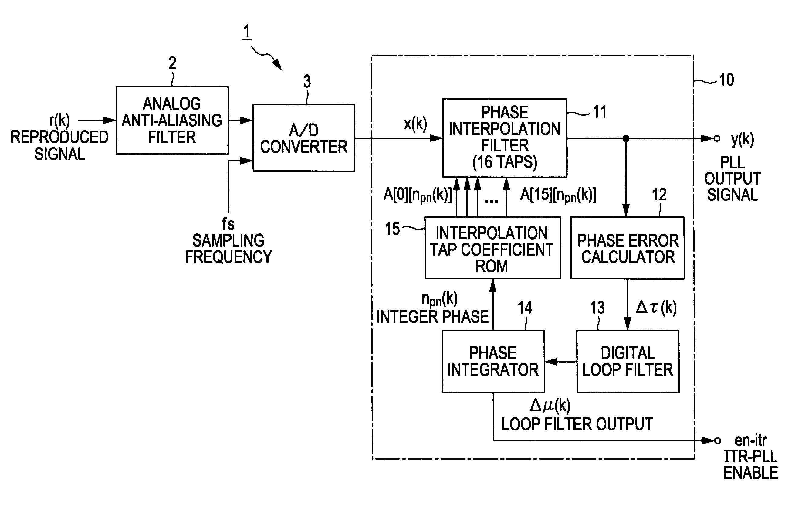
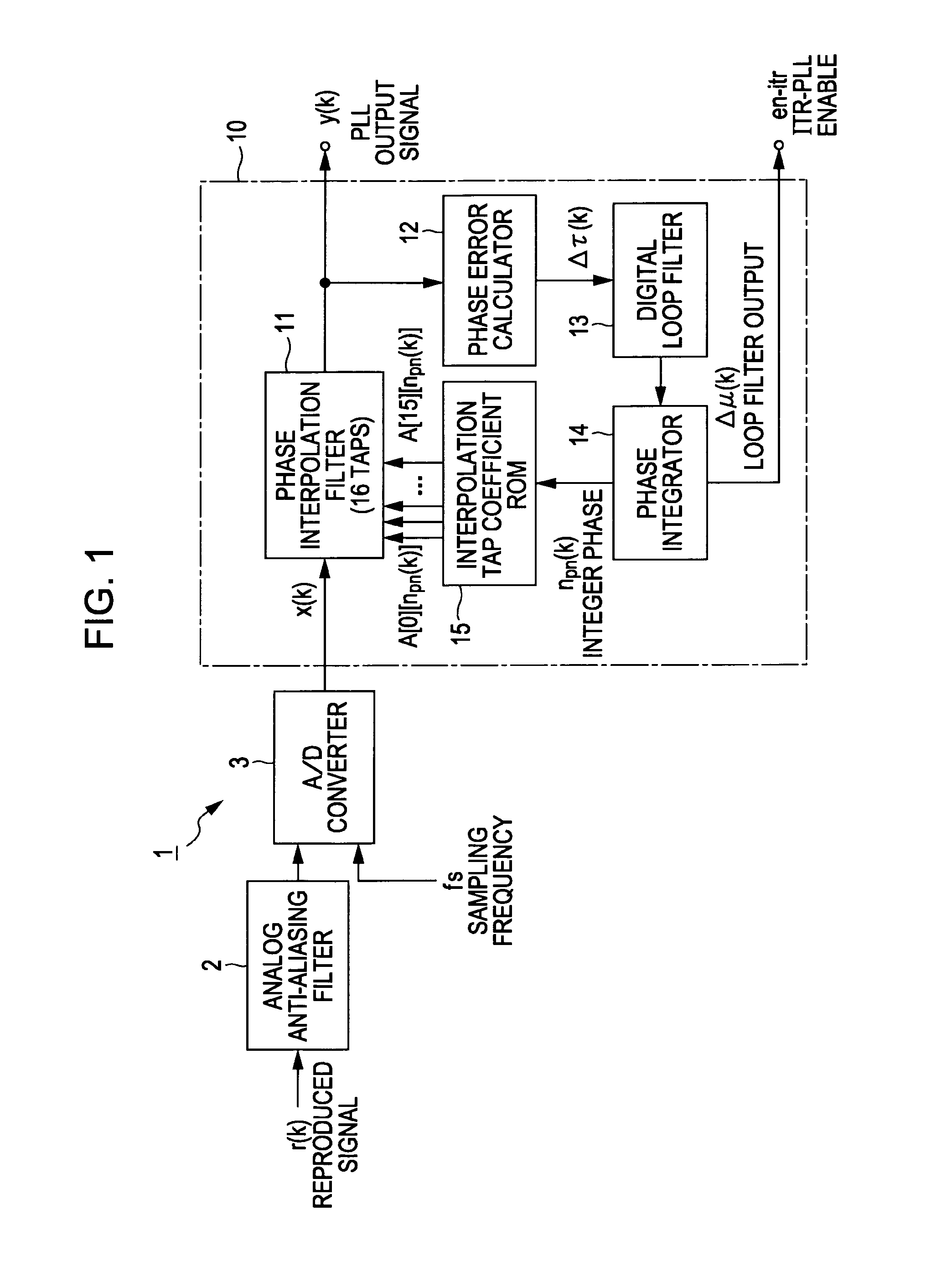
[0057]FIG. 1 is a block diagram of an optical disk reproduced signal processor 1 including an ITR digital PLL circuit.

[0058] The optical disk reproduced signal processor 1 includes, as shown in FIG. 1, an analog anti-aliasing filter 2, an A / D converter 3 that performs analog-to-digital conversion, and an ITR digital PLL circuit 10.

[0059] The ITR digital PLL circuit 10 includes a phase interpolation filter 11 that interpolates an output signal of the A / D converter 3, a phase error calculator 12 that calculates a phase error between the input and the output of the phase interpolation filter 11, a digital loop filter 13 that filter...


PUM

PropertyMeasurementUnit
frequencyaaaaaaaaaa
phase locking methodaaaaaaaaaa
phase interpolationaaaaaaaaaa

Abstract

A method determines tap coefficients of a phase interpolation finite impulse response (FIR) filter with respect to a digital-signal phase-locked loop processing apparatus including an A / D converter receiving a reproduced signal serving as digital data and sampling the received reproduced signal at a frequency higher than a data rate frequency and a PLL portion performing phase locking of the reproduced signal by filtering the sampled reproduced signal obtained by the A / D converter using the phase interpolation FIR filter and outputting a data sequence of the phase-locked reproduced signal. The method includes providing an adaptive equalization FIR filter at the data rate frequency at a stage subsequent to the PLL portion and determining the tap coefficients of the phase interpolation FIR filter using, as estimated values, FIR filter tap coefficients of the adaptive equalization FIR filter, which are converged so as to achieve a minimum mean square error.

Description

CROSS REFERENCES TO RELATED APPLICATIONS [0001] The present invention contains subject matter related to Japanese Patent Application JP 2005-239034 filed in the Japanese Patent Office on Aug. 19, 2005, the entire contents of which are incorporated herein by reference. BACKGROUND OF THE INVENTION [0002] 1. Field of the Invention [0003] The present invention relates to a method and apparatus for determining tap coefficients in phase locking in reproducing recorded or transmitted digital data and to a method and apparatus for performing phase locking in reproducing recorded or transmitted digital data. [0004] 2. Description of the Related Art [0005] A storage device using magnetic or optical recording technology or the like has an analog signal processing block including an analog circuit and a digital signal processing block including a digital circuit, which are circuits for playing back a recorded signal. [0006] Due to recent developments in semiconductor manufacturing technology, t...

Claims


Application Information

Patent Timeline
Patent Type & Authority Applications(United States)
IPC IPC(8): G11B5/09
CPCG11B20/10037G11B20/10046G11B20/10111G11B20/10212G11B20/10425G11B20/10481G11B2220/2541
Inventor KAJIWARA, YOSHIYUKI
Owner SONY CORP
Learn More